Route planning method and device for unmanned aerial vehicle

A drone and path technology, applied in the field of drones, can solve the problem of inapplicable precise planning of the path with the least collision probability between drones and obstacles, and achieve the effect of ensuring safety

Inactive Publication Date: 2016-11-09
GUANGZHOU XAIRCRAFT TECH CO LTD
View PDF10 Cites 38 Cited by
  • Summary
  • Abstract
  • Description
  • Claims
  • Application Information

AI Technical Summary

Problems solved by technology

[0004] The embodiment of the present invention provides a UAV path planning method to solve the problem that the path planning method in the prior art is not suitable for accurately planning the path with the least collision probability between the UAV and obstacles

Method used


Image

  • Route planning method and device for unmanned aerial vehicle
  • Route planning method and device for unmanned aerial vehicle
  • Route planning method and device for unmanned aerial vehicle

Examples


Embodiment 1

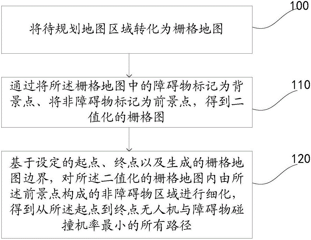
[0026] Such as figure 1 As shown, the embodiment of the present invention discloses a UAV path planning method, including: step 100 to step 120 .

[0027] Step 100, converting the map area to be planned into a grid map.

[0028] At present, most of the maps used for navigation are vector graphics, and the map contains a large amount of information, including: geographical location information and landform information. Vector graphics are lines, planes, and volumes drawn by a series of coordinates and functions, which can be zoomed indefinitely and have high definition. In the embodiment of the present invention, it is only necessary to know the topographical information of a certain geographical location, and it is not necessary to perform a zoom operation on the map. Therefore, a grid map may be used. And, pixel-based raster maps facilitate refinement.

[0029] During specific implementation, the UAV flight map data to be planned can be obtained by reading the electronic m...

Embodiment 2

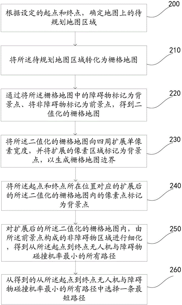
[0036] Such as figure 2 As shown, the embodiment of the present invention discloses a UAV path planning method, including: step 200 to step 260 .

[0037] Step 200, according to the set start point and end point, determine the map area to be planned on the map;

[0038] First, according to the starting point and the ending point of the set path, an area including the starting point and the ending point on the map used to plan the flight path, and the range is slightly larger than the range determined by the starting point and the ending point is used as the map area to be planned. For example, if the starting point is set to be Beijing and the end point is Tianjin, then only the map ranges of Hebei Province and Beijing City need to be selected as the map area to be planned. During specific implementation, a minimum circular or rectangular area including the starting point and end point can be determined according to the set starting point and end point, and then the circular...

Embodiment 3

[0076] Correspondingly, see Figure 8 , the present invention also discloses a UAV path planning device, comprising:

[0077] A rasterization module 800, configured to convert the map area to be planned into a raster map;

[0078] The binarization module 810 is used to obtain a binarized raster map by marking obstacles in the raster map obtained by the rasterization module 800 as background points and non-obstacles as foreground points;

[0079] The path refinement module 820 is configured to refine the non-obstacle area formed by the foreground points in the binarized grid map based on the set start point, end point and generated grid map boundary, to obtain All paths from the start point to the end point with the least probability of the UAV colliding with obstacles.

[0080] Optionally, as in Figure 9 As shown, the path refinement module 820 includes:

[0081] A condition setting unit 8201, configured to expand the binarized grid map to a single pixel width around, and...


PUM


Abstract

The invention provides a route planning method and device for an unmanned aerial vehicle and belongs to the technical field of computers. The method comprises steps as follows: a to-be-planned map area is converted into a raster map; barriers in the raster map are marked as background points, non-barriers are marked as foreground points, and a binarized raster map is obtained; a non-barrier area formed by the foreground points in the binarized raster map is detailed on the basis of a set starting point, an end point and the boundary of the generated raster map, all routes where the unmanned aerial vehicle least probably collides with barriers from the starting point to the end point are obtained, and the problem that a route planning method in the prior art is not applicable to accurate planning of the routes where the unmanned aerial vehicle least probably collides with the barriers is solved. The non-barrier area is detailed, all the routes where the unmanned aerial vehicle least probably collides with the barriers from the starting point to the end point are obtained, and the flight safety is guaranteed.

Description

technical field [0001] The invention relates to the technical field of unmanned aerial vehicles, in particular to a method and device for path planning of an unmanned aerial vehicle. Background technique [0002] At present, UAV path planning methods generally focus on optimal path planning, such as the shortest flight distance, the least time-consuming, and the least energy consumption of UAVs. When planning the optimal path, the path planning methods used include ant colony algorithm, neural network algorithm, artificial field of view algorithm, Dijkstra algorithm, A* algorithm and so on. The above-mentioned path planning method focuses on the length of the flight path of the UAV when calculating the optimal path, but does not have strict requirements on the distance between the path and obstacles, and is more suitable for open flight environments. It can be seen that the above path planning method is not suitable for the UAV flight environment with many obstacles and com...

Claims


Application Information

Patent Timeline
IPC IPC(8): G01C21/20
CPCG01C21/20
Inventor 陈有生
Owner GUANGZHOU XAIRCRAFT TECH CO LTD
Why Eureka
Try Eureka