Circular dichroism spectrum and refractive index measuring system based on linear polarized light incidence

A linearly polarized light, circular dichroism technology, applied in the field of molecular spectroscopy, can solve the problems of expensive instruments, increased circular dichroism test time, and high maintenance costs, and achieves simple test methods, novel measurement methods, and low overall machine cost. Effect

Active Publication Date: 2016-11-09
FUZHOU UNIV
View PDF6 Cites 6 Cited by
  • Summary
  • Abstract
  • Description
  • Claims
  • Application Information

AI Technical Summary

Problems solved by technology

In this way, there is a minimum requirement for the sample, so it cannot realize the measurement of very few chiral samples; secondly, because the photoelastic modulator used can only modulate one specific wavelength at a time, it is necessary to obtain a wide range of For circular dichroism signals on the spectrum, the incident light must pass through the monochromator for wavelength scanning, and the scanning measures the circular dichroism value at each wavelength, which leads to an increase in the circular dichroism test time for the entire wide spectrum
Third, the traditional circular dichroism spectroscopy system is

Method used


Image

  • Circular dichroism spectrum and refractive index measuring system based on linear polarized light incidence
  • Circular dichroism spectrum and refractive index measuring system based on linear polarized light incidence
  • Circular dichroism spectrum and refractive index measuring system based on linear polarized light incidence

Examples


Embodiment Construction

[0020] The technical solution of the present invention will be specifically described below in conjunction with the accompanying drawings.

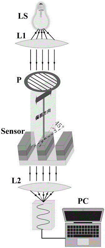
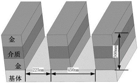
[0021] The present invention is a circular dichroism and refractive index measurement system based on linearly polarized light incidence, which includes a supercontinuum light source, a first lens, an adjustable polarizer, a one-dimensional periodic metal groove structure, a second lens, and a spectrometer; the supercontinuum The wide-spectrum continuous light emitted by the continuous light source passes through the first lens to obtain parallel light, and then modulated by an adjustable polarizer into a linearly polarized light at a first angle with the one-dimensional periodic metal groove structure, which is incident on the one-dimensional The chiral sample to be tested on the surface of the periodic metal groove structure, and then the transmitted light is collected by the spectrometer after being focused by the second lens; then the ...


PUM


Abstract

The invention relates to a circular dichroism spectrum and refractive index measuring system based on linear polarized light incidence. Wide-spectrum continuous light emitted by a super-continuous light source passes through a first lens and is adjusted to obtain parallel light, and the parallel light is modulated through an adjustable polarizer into linear polarized light, wherein the linear polarized light and a one-dimensional period metal groove structure form a first angle; after the linear polarized light is emitted into a to-be-measured chiral sample attached to the surface of the one-dimensional period metal groove structure, transmission light is focused by a second lens to be collected by a spectrograph; the adjustable polarizer is further adjusted, and the parallel light is modulated into linear polarized light, wherein the linear polarized light and the one-dimensional period metal groove structure form a second angle, and the second angle and the first angle are oppositely symmetrical; then after the linear polarized light is emitted in the to-be-measured chiral sample, the transmission light is focused by the second lens to be collected by the spectrograph; according to the transmission spectrums collected twice, a circular dichroism spectrum single and the refractive index of the to-be-measured chiral sample can be calculated and obtained. According to the circular dichroism spectrum and refractive index measuring system, a test method is simple; as adopted elements are universal components, the whole machine cost of the system is quite low, and the system has the quite large popularization value.

Description

technical field [0001] The invention relates to the field of molecular spectroscopy, in particular to a circular dichroism spectrum and a refractive index measurement system based on linearly polarized light incidence. Background technique [0002] In many drug molecules, the molecular formulas of enantiomers are exactly the same, but the configuration of atoms or atomic groups in space is different, and they are mirror images of each other. We call such molecules that cannot coincide with their mirror image structures chiral molecules. Many biomolecules such as proteins, DNA, amino acids, etc. cannot coincide with their own mirror images due to their spatial structure and structure characteristics, and they are also chiral molecules. The spatial chiral characteristics of these molecules are directly related to the functions of the molecules, so the chiral analysis of chiral molecules is very important. [0003] At present, the most direct and effective technique for molec...

Claims


Application Information

Patent Timeline
IPC IPC(8): G01N21/19G01N21/41G01N21/01
CPCG01N21/01G01N21/19G01N21/41G01N21/4133G01N2021/0112
Inventor 钟舜聪姚海子
Owner FUZHOU UNIV
Why Eureka
Try Eureka