Defect region detection method and device

A region and defect technology, which is applied in the field of defect region detection methods and devices, can solve the problem of low efficiency in determining the target difference threshold, and achieve the effect of improving efficiency

Active Publication Date: 2016-11-09
KUNSHAN GO VISIONOX OPTO ELECTRONICS CO LTD
View PDF5 Cites 26 Cited by
  • Summary
  • Abstract
  • Description
  • Claims
  • Application Information

AI Technical Summary

Problems solved by technology

[0010] The embodiment of the present application provides a defect region detection method to solve the problem in the prior art that the determination of the target difference threshold by manual attempts leads to low determination efficiency of the target difference threshold
[0011] The embodiment of the present application also provides a defect area detection device, which is used to solve the problem in the prior art that the determination of the target difference threshold by manual attempts leads to low determination efficiency of the target difference threshold

Method used


Image

  • Defect region detection method and device
  • Defect region detection method and device
  • Defect region detection method and device

Examples


Embodiment 1

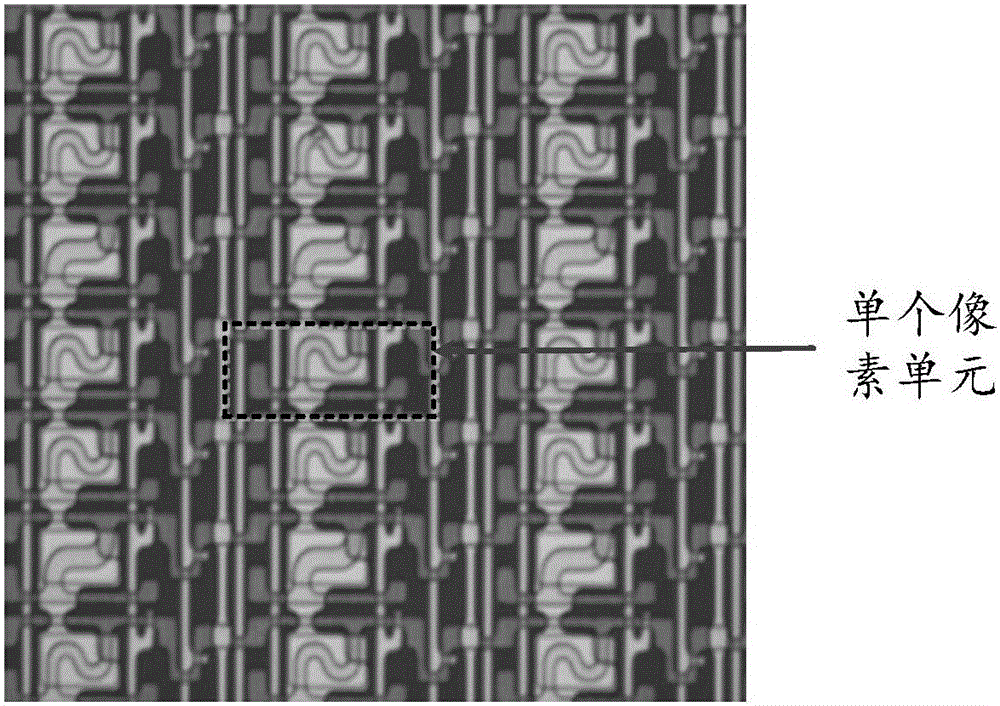
[0055] In order to solve the problem in the prior art that determining the target difference threshold by manual attempts leads to low determination efficiency of the target difference threshold, Embodiment 1 of the present application provides a defect area detection method. The execution subject of the method for detecting a defect region provided in the embodiment of the present application may be a defect detection system, for example, a defect detection system for detecting a defect region in a panel, and the like.

[0056] For the convenience of description, the implementation of the method will be introduced below by taking the defect detection system for detecting the defect area in the panel as an example where the subject of execution of the method is. It can be understood that the execution subject of the method is a defect detection system for detecting defect areas in the panel is only an exemplary description, and should not be understood as a limitation of the me...

Embodiment 2

[0090] In order to solve the problem in the prior art that determining the target difference threshold by manual attempts leads to low determination efficiency of the target difference threshold, Embodiment 2 of the present application provides a defect area detection device. The structural schematic diagram of the defect area detection device is as follows: Figure 4 As shown, it mainly includes the following functional units:

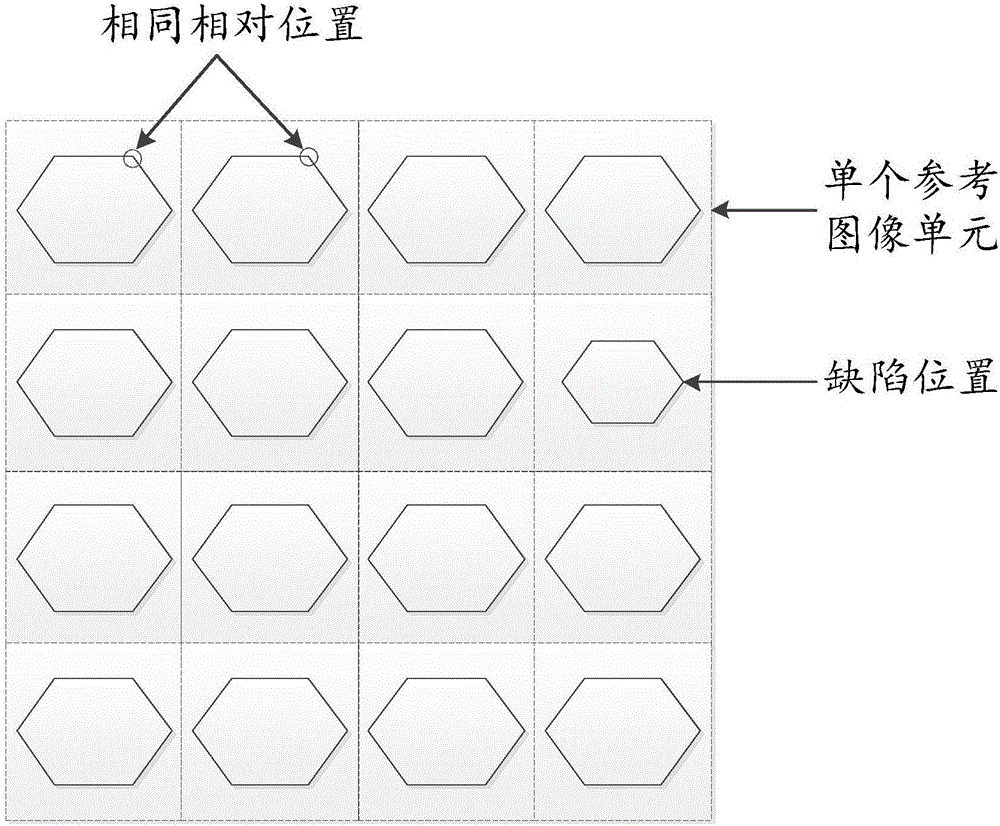
[0091] The coordinate parameter receiving unit 21 is configured to receive the coordinate parameters of each first pixel point in the grayscale image input by the user, and the first pixel point is a pixel point on the grayscale image corresponding to the actual defect area in the detected area;

[0092] A grayscale value determination unit 22, configured to determine the grayscale value of each first pixel point and the grayscale value of each second pixel point according to the coordinate parameters of each first pixel point in the grayscale image i...


PUM


Abstract

The invention discloses a defect region detection method, which is used for solving a problem of low target difference value threshold determination efficiency caused by a mode of determining a target difference value threshold through manual attempts in the prior art. The method comprises the steps of receiving coordinate parameters of each first pixel point inputted by a user in a grayscale image, wherein the first pixel points are pixel points on the grayscale image corresponding to actual defect regions in a detected region; determining a grayscale value of each first pixel point and a grayscale value of each second pixel point according to the coordinate parameters of each first pixel point inputted by the user in the grayscale image, wherein the second pixel points are pixel points, which are the same in relative position with the first pixel points, in a reference image unit; respectively calculating a different value between the grayscale value of each first pixel point and a grayscale value of the second pixel point which is the same in relative position with the corresponding first pixel point; and using the difference value meeting a target difference value threshold condition as the target difference value threshold. The invention further discloses a defect region detection device.

Description

technical field [0001] The present application relates to the technical field of semiconductors, and in particular to a defect region detection method and device. Background technique [0002] With the rapid development of electronic technology, electronic components are developing in the direction of miniaturization and density. For example, for a display panel, the display panel will be composed of multiple pixel units, such as figure 1 Shown is the pixel unit after image enlargement. During the manufacturing process of display panels, there may be defects in the panels due to process problems, making it difficult to ensure the uniformity of display brightness of the display panels. How to improve the yield rate of display panels has become a great concern of every display panel manufacturer. The problem. [0003] In order to find defects in the display panel, the display panel needs to be inspected, and then the process can be improved in a targeted manner so as to inc...

Claims


Application Information

Patent Timeline
Patent Type & Authority Applications(China)
IPC IPC(8): G06T7/00
CPCG06T7/001G06T2207/30121
Inventor 白帆
Owner KUNSHAN GO VISIONOX OPTO ELECTRONICS CO LTD
Why Eureka
Try Eureka