Environment test device refrigerating system and energy-saving working condition fast determination method thereof

The technology of an environmental test device and a refrigeration system is applied in the field of rapid determination of the energy-saving working conditions of the refrigeration system of the environmental test device, which can solve the problems of low design efficiency, long time consumption, limitation of extreme conditions, etc., and achieve the effect of fast and efficient determination and improvement of efficiency.

Inactive Publication Date: 2013-05-15
CHINA ELECTRONICS TECH GROUP CORP NO 16 INST
View PDF5 Cites 9 Cited by
  • Summary
  • Abstract
  • Description
  • Claims
  • Application Information

AI Technical Summary

Problems solved by technology

At present, the refrigeration system of the environmental test device mainly adopts single-stage or two-element cascade refrigeration. During the design process of the refrigeration system, enterprises may use manual calculation or their own experience or use such as Solkane, REFLUENT or other refrigeration system design. However, there are disadvantages such as low design efficiency, long time-consuming, limitation of extreme conditions, limitation of refrigerant types and limitation of a single system.

Method used


Image

  • Environment test device refrigerating system and energy-saving working condition fast determination method thereof
  • Environment test device refrigerating system and energy-saving working condition fast determination method thereof

Examples


Embodiment Construction

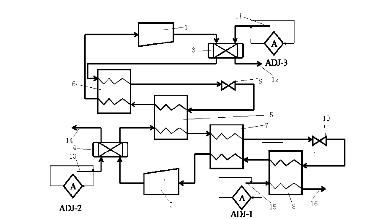
[0043] Such as figure 2 As shown, a refrigeration system of an environmental test device includes a high-temperature stage and a low-temperature stage, and the high-temperature stage includes a compressor-1, and the exhaust pipe of the compressor-1 is connected to the inlet of a condenser 3, The outlet of the condenser 3 is connected to the inlet of the first pipeline of the regenerator 6, the outlet of the first pipeline is connected to the inlet of the expansion valve 9, and the outlet of the expansion valve 9 is connected to the inlet of the first pipeline of the condensing evaporator 5, and the outlet of the first pipeline is connected to the inlet of the first pipeline of the condensing evaporator 5. The outlet of a pipeline is connected to the inlet of the second pipeline of the regenerator-6, the outlet of the second pipeline is connected to the suction pipe of the compressor-1, and the condenser 3 has a cooling water inlet 11 and cooling water outlet 12; the low-tempe...


PUM


Abstract

The invention discloses an environment test device refrigerating system and an energy-saving working condition fast determination method of the environment test device refrigerating system. The environment test device refrigerating system and the energy-saving working condition fast determination method of the environment test device refrigerating system comprises: 1. based on HYSYS, a suitable physical property method and a suitable parameter output mode are selected according to refrigerant properties; 2. special design of process procedures of a refrigerating system is conducted; 3. key point working condition parameters are input and are dynamically calculated to acquire working condition design parameters; and 4. condition ranges are defined, target technical parameters are optimized to embody energy-saving effect. The environment test device refrigerating system and the energy-saving working condition fast determination method of the environment test device refrigerating system can greatly improve efficient of design of the refrigerating system and confirmation of the working condition parameters, overcome all kinds of adverse factors such as limited essential data and limited condition selection of refrigerating fluid of design software of some refrigerating systems, and meanwhile timely design a technological process and acquire the most energy-saving process state parameters according to different environment, timely calculate air quantity and confirm air volume according to the size of loads, and therefore the advantages that the working condition parameters of the refrigerating system can be fast and efficiently confirmed are truly demonstrated.

Description

technical field [0001] The invention relates to the technical field of refrigeration systems, in particular to a method for quickly determining energy-saving working conditions of a refrigeration system of an environmental test device. Background technique [0002] The refrigeration system in most environmental test devices can be said to be its core component. The stable operation of the refrigeration system directly determines the reliability of the environmental test device. At the same time, the energy consumption of the refrigeration system also accounts for a large part of the total load of the environmental test device. Therefore, enterprises must consider the scientific design of refrigeration systems and the principle of minimizing energy consumption when designing production processes or new product development processes. At present, the refrigeration system of the environmental test device mainly adopts single-stage or two-element cascade refrigeration. During the...

Claims


Application Information

Patent Timeline
Patent Type & Authority Applications(China)
IPC IPC(8): F25B7/00F25B41/06F25B49/02F25B41/30
Inventor 陆宏权李港生邱彪
Owner CHINA ELECTRONICS TECH GROUP CORP NO 16 INST
Why Eureka
Try Eureka