Power distribution cabinet based on cable fixing and adjusting structure

A technology for adjusting the structure and power distribution cabinet, which is applied in substation/power distribution device housing, electrical components, busbar/line layout, etc. It can solve the problem of insufficient stability of cable connection, achieve convenient installation and operation, significant effect, and simplify fixing operation Effect

Inactive Publication Date: 2016-11-09
SICHUAN XINGZHI ZHIHUI INTPROP OPERATION CO LTD
View PDF5 Cites 7 Cited by
  • Summary
  • Abstract
  • Description
  • Claims
  • Application Information

AI Technical Summary

Problems solved by technology

[0005] The purpose of the present invention is to solve the problem in the prior art that the connection of the cable at the connection in the distribution box is not stable enough during the cable wiring operation, and to provide a cable-based fixing system that is stable in connection and effectively avoids the influence on the connection during the wiring operation. Adjust the structure of the power distribution cabinet

Method used


Image

  • Power distribution cabinet based on cable fixing and adjusting structure
  • Power distribution cabinet based on cable fixing and adjusting structure
  • Power distribution cabinet based on cable fixing and adjusting structure

Examples


Embodiment 1

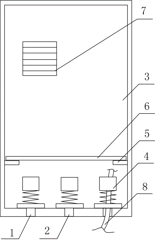
[0030] Power distribution cabinets based on cable fixed and adjusted structures, such as figure 1 As shown, it includes a power distribution cabinet body 3 with a cable inlet 1 and a cable outlet 2, and the cable inlet 1 and the cable outlet 2 in the power distribution cabinet body 3 are provided with anti-pull pieces 4;

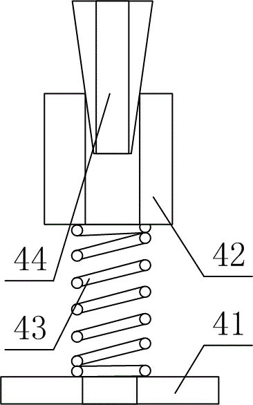
[0031] like figure 2 As shown, the anti-pull member 4 includes a baffle 41 fixed on the power distribution cabinet body 3 and having a first cable through hole, and a fixing member 42 with a second cable through hole, and the two ends are respectively connected to the baffle The spring 43 of the plate 41 and the fixing member 42, and the cable fixing adjustment structure 44 arranged above the second cable through hole, such as figure 2 shown.

[0032] The shape of the cable fixing and adjusting structure 44 is a tapered structure, the diameter of the cable fixing and adjusting structure 44 gradually decreases along the central axis toward the fixing memb...

Embodiment 2

[0037] The difference between this embodiment and Embodiment 1 is that this embodiment optimizes the detachable partition 6, and the specific structure is set as follows:

[0038] Both the cable inlet 1 and the cable outlet 2 are located at the bottom of the power distribution cabinet body 3, and a protruding block 5 is arranged on the power distribution cabinet body 3 above the anti-pull member 4, on which a protruding block 5 is placed. Remove the separator 6.

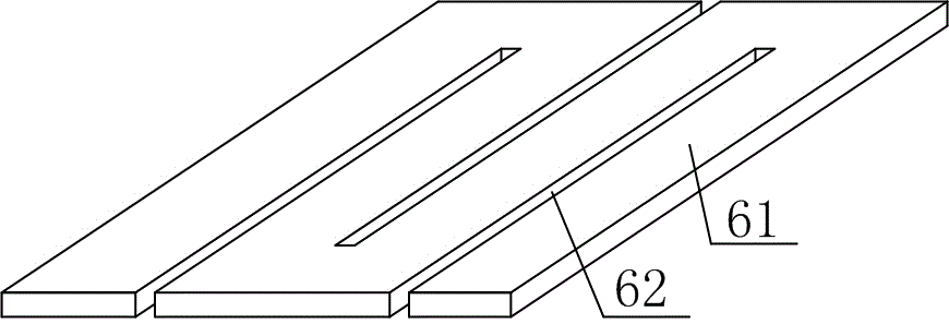
[0039] like image 3 As shown, the detachable partition 6 consists of a plate body 61 and is arranged on a through groove 62 with one end open on the plate body 61 .

[0040] At the same time, the main body 3 of the power distribution cabinet is also provided with an air vent 7 .


PUM


Abstract

The invention discloses a power distribution cabinet based on a cable fixing and adjusting structure, which mainly solves the problem in the prior art that a cable cannot be stably connected with a connection part inside a power distribution cabinet during the cable wiring operation. The power distribution cabinet comprises a power distribution cabinet body and an anti-pulling piece. The anti-pulling piece comprises a baffle plate fixed on the power distribution cabinet body and provided with a first cable through hole, a fixing part provided with a second cable through hole, a spring with the two ends thereof respectively connected with the baffle plate and the fixing part, and a cable fixing and adjusting structure arranged above the second cable through hole. The cable fixing and adjusting structure is of a conical structure. The diameter of the cable fixing and adjusting structure is gradually reduced along the central axis towards the direction of the fixing part. The central connecting line between the first cable through hole and the second cable through hole is on the same straight line with the central axis of the spring. The power distribution cabinet is stable in connection effect and the influence of the cable wiring operation on the connection part thereof is effectively avoided.

Description

technical field [0001] The invention relates to a power distribution cabinet, in particular to a power distribution cabinet based on cable fixing and adjusting structure. Background technique [0002] The power distribution cabinet is a kind of electrical equipment. The main function of the power distribution cabinet is to open and close, control and protect electrical equipment during the process of power generation, transmission, distribution and power conversion in the power system. The components in the power distribution cabinet are mainly composed of circuit breakers, isolating switches, load switches, operating mechanisms, transformers and various protection devices. There are many classification methods for power distribution cabinets. For example, according to the installation method of circuit breakers, it can be divided into removable power distribution cabinets and fixed power distribution cabinets; or according to different cabinet structures, it can be divided ...

Claims


Application Information

Patent Timeline
Patent Type & Authority Applications(China)
IPC IPC(8): H02B1/20H02B1/30H02G3/02
CPCH02B1/202H02B1/30H02G3/02
Inventor 谭逢林
Owner SICHUAN XINGZHI ZHIHUI INTPROP OPERATION CO LTD
Why Eureka
Try Eureka