Portable camera device to be attached to a remote manipulator gripper

A portable, manipulator technology that is applied in the direction of mechanical equipment, instrument parts, instruments, etc., to solve the problems of bulkiness, refocusing, tedious precautions and work

Active Publication Date: 2016-11-09
COMMISSARIAT A LENERGIE ATOMIQUE ET AUX ENERGIES ALTERNATIVES
View PDF6 Cites 3 Cited by
  • Summary
  • Abstract
  • Description
  • Claims
  • Application Information

AI Technical Summary

Problems solved by technology

Since the position of the periscope is fixed, the periscope usually has the disadvantage of being bulky and providing limited additional vision for only a fraction of the capacity of the room; this is why a camera is an excellent supplementary tool, since the camera is an integral part of the device. Inexpensive, portable and light weight item, therefore capable of being moved to any position, and the reason for this is that the camera can also be oriented in all directions inside the room, allowing almost complete control of the volume of the shielded room in which the camera is arranged vision coverage
This device is convenient, but has the following disadvantages: the camera must be refocused before each operation, the support is located at a variable distance relative to the scene to be observed
US 2010 / 0158656 A and JP 2007-288010 A disclose such devices in which the camera is mounted on an arm by means of a fixed support or a support which is only manually detachable; The arm has to be taken out of the room, which requires tedious precautions and work to be done according to safety codes
US 2014 / 055597 A discloses a device in which the camera is mounted on such a support by means of a connecting piece enabling easy replacement of the camera by remote manipulation, which is advantageous and corresponds to an object of the present invention; However, the support must remain on the arm, so that if the support is also to be changed or adjusted in another way, the disadvantages of the previous device remain

Method used


Image

  • Portable camera device to be attached to a remote manipulator gripper
  • Portable camera device to be attached to a remote manipulator gripper
  • Portable camera device to be attached to a remote manipulator gripper

Examples


Embodiment Construction

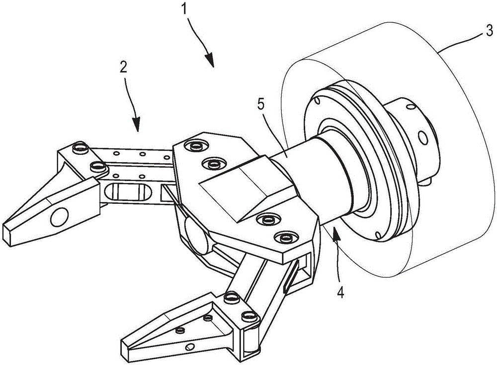
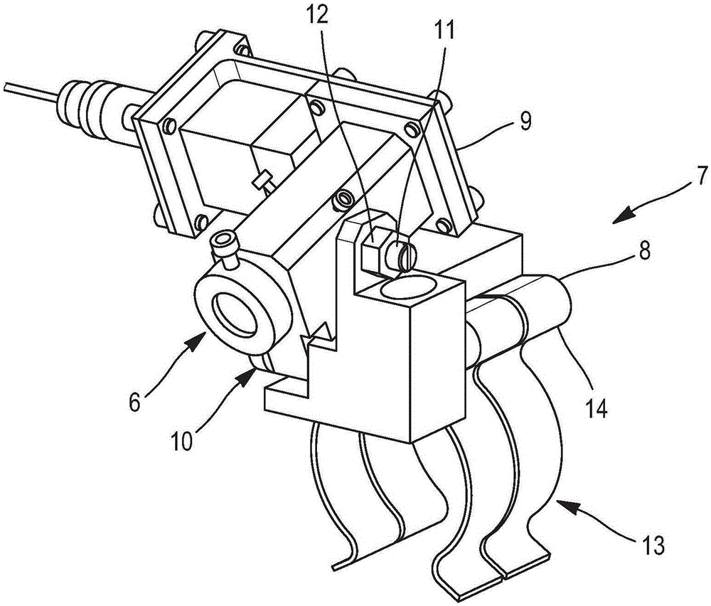
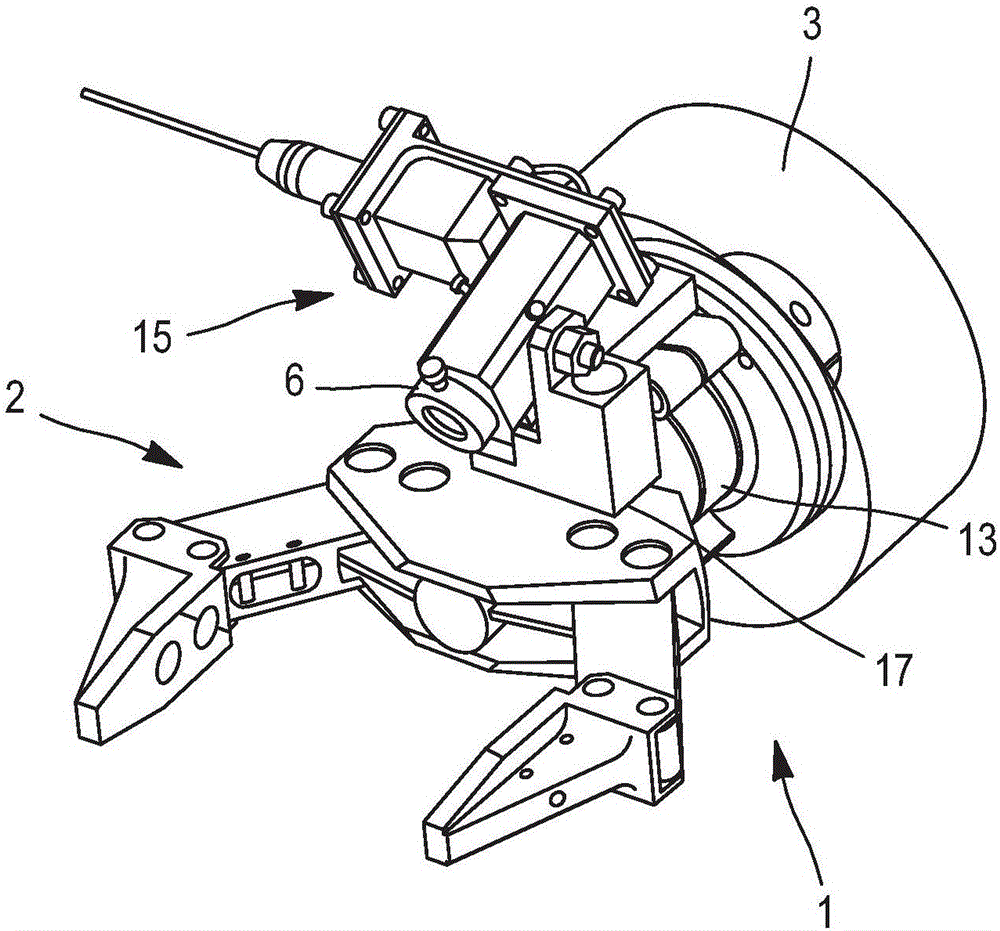
[0025] The invention is intended for telemanipulator arms of a common type and comprises at the end a tool such as a clamp 2 connected to the distal section 3 of the arm 1 by a wrist joint 4 . The wrist joint 4 is here a coupling designed to remain sealed and thus includes an outer sleeve 5 which is perfectly cylindrical and smooth ( figure 1 ). The device 15 of the present invention includes a camera 6 ( figure 2 ), the camera 6 is mounted on a support 7 including a fixed part 8 and a movable part 9 . The camera 6 is fixed to the movable part 9 . The fixed part 8 and the movable part 9 are connected to each other by a joint 10 provided with a brake 11 , ie a mechanism for locking the joint 10 . The fixed part 8 includes a spring 13 located below its bottom face 14 opposite the movable part 9 and the camera 6 . The device 15 of the present invention can be as image 3 Mounted on the arm 1 as shown, the spring 13 is arranged around the sleeve 5, the camera 6 is placed jus...


PUM


Abstract

A camera (6) for viewing the inside of a shielded cell comprises a support (7) fitted with a clip-shaped spring (13) for mounting it on a remote manipulation arm performing the task that is to be viewed, by means of another arm, applying only a force to part the branches of the spring, after which the camera (6) is firmly held, while at the same time being able to be removed without difficulty. A stop means is added to ensure that the camera adopts the correct angular position by preventing the support thereof rotating about the arm, thus making it possible for it to be positioned correctly using other remote manipulation means.

Description

technical field [0001] The subject of the invention is a portable camera device to be fixed with a telemanipulator clamp. Background technique [0002] During telepilot activities, the operators view the scene in which they are working by passing through a window in the same wall next to where the operator actuated telemanipulator passes through this same wall. However, some off-center locations in the room, or locations that are obscured by objects located inside, are difficult to see from this direct view. Therefore, these chambers are equipped with vision aids, such as periscopes or cameras. Since the position of the periscope is fixed, the periscope usually has the disadvantage of being bulky and providing limited additional vision for only a fraction of the capacity of the room; this is why a camera is an excellent supplementary tool, since the camera is an integral part of the device. Inexpensive, portable and light weight item, therefore capable of being moved to an...

Claims


Application Information

Patent Timeline
Patent Type & Authority Applications(China)
IPC IPC(8): B25J1/08B25J3/02B25J19/02H04N5/225
CPCB25J1/08B25J3/02B25J19/023H04N23/50B26D5/007B25J1/10F16M13/02G12B9/08
Inventor 弗朗索瓦·戈宾迈克尔·根尼松克里斯多福·布內
Owner COMMISSARIAT A LENERGIE ATOMIQUE ET AUX ENERGIES ALTERNATIVES
Why Eureka
Try Eureka