
Furniture hinge comprising a damper and a spring

A buffer and furniture technology, applied in the field of furniture hinges, can solve the problems of increasing the manufacturing cost of furniture hinges, increasing component costs, and high installation costs

Active Publication Date: 2016-11-16
SAMET KALIP VE MADENI ESYA SAN TIC AS
View PDF11 Cites 3 Cited by
  • Summary
  • Abstract
  • Description
  • Claims
  • Application Information

AI Technical Summary

Problems solved by technology

The additional covering increases the component outlay and thus the production costs for the furniture hinges
Furthermore, additional components have to be arranged in the limited interior space of the hinge cup, which greatly limits the space available for the buffer
Separate installation of dampers, shields and springs leads to high installation costs

Method used


Image

  • Furniture hinge comprising a damper and a spring
  • Furniture hinge comprising a damper and a spring
  • Furniture hinge comprising a damper and a spring

Examples


Embodiment Construction

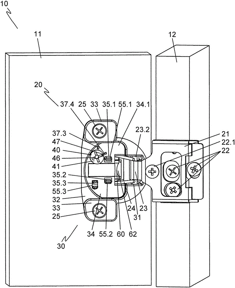
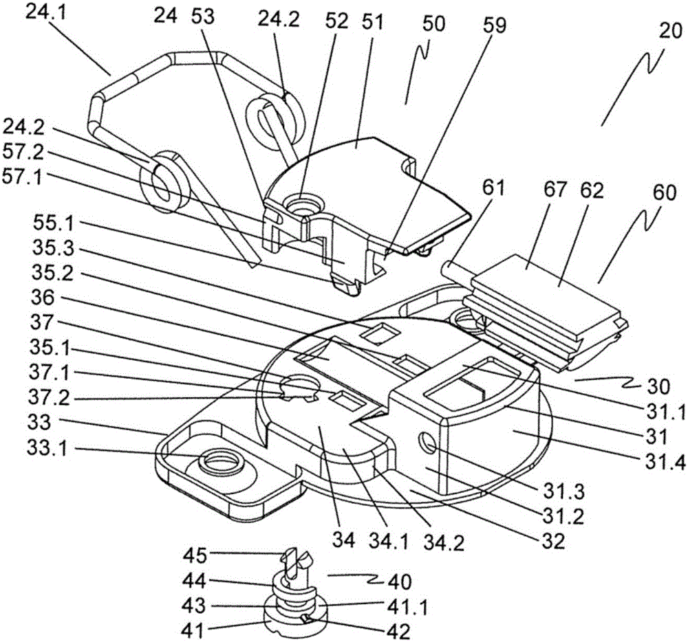
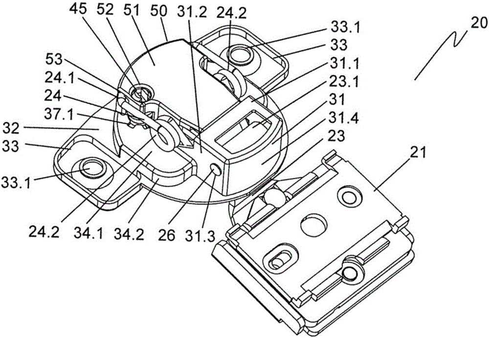
[0030] figure 1A detail of a piece of furniture 10 with a furniture hinge 20 is shown. The furniture hinge 20 connects the door 11 pivotably to the frame 12 of the furniture 10 . For this purpose, the stop element 21 is connected to the frame 12 and the hinge cup 30 is connected to the door 11 . The stop element 21 is fastened and aligned on the frame 22 via the mounting and adjustment element 22 . The hinge cup 30 is inserted into a hole in the door 11 and is screwed to the door 11 by means of screws 25 which are guided by side flanges 33 molded onto the hinge cup 30 at the side. The articulation lever 23 articulated on the hinge cup 30 within the centering region 31 connects the hinge cup 30 to the stop element 21 . The articulating lever 23 is screwed onto the stop element 21 by means of a fastening screw 22.1. The centering region 31 forms, starting from the outer support surface 32 , a depression which transitions into a mounting region 34 , which is likewise designed...


PUM


Abstract

The invention relates to a furniture hinge comprising a stop element and a hinge cup which is pivotally connected to said stop element by means of an articulated lever, a damper being arranged in a housing, said housing being connected to the hinge cup by means of securing means, and a spring being functionally connected to the hinge cup and the stop element or the articulated lever. According to the invention, the housing comprises a spring seat by means of which said spring is secured to the housing. This achieves a damped, compact furniture hinge which has a spring to support at least the closing action, and which is easy to mount.

Description

technical field [0001] The invention relates to a furniture hinge having a stop element and a hinge cup pivotably connected to the stop element via a hinge lever, wherein the damper is arranged in a housing, wherein the housing is connected to the hinge cup via a fastening element, and In this case, the spring is operatively connected to the hinge cup and the stop element or the articulation lever. Background technique [0002] Such a furniture hinge is known from WO 2010 / 108201 A1. The furniture hinge described therein has a damper which is arranged in the housing and which is operatively connected to the hinge cup and the stop part or the joint lever connecting the hinge cup and the stop part. The housing can be installed into the hinge cup from above and is arranged completely inside the hinge cup in the installed position. For this purpose, the housing is connected to the hinge cup via fastening elements, preferably in the form of a self-positioning stop connection. T...

Claims


Application Information

Patent Timeline
Patent Type & Authority Applications(China)
IPC IPC(8): E05F3/20
CPCE05F3/20E05Y2900/20E05F5/02E05Y2201/21E05Y2201/264E05Y2201/214E05Y2201/256E05Y2201/22E05F5/006
Inventor Ü·基伦希E·卡普尔
Owner SAMET KALIP VE MADENI ESYA SAN TIC AS
Learn More