Fixing part resistance structure of welded meshes

A technology of welding mesh and resistance structure, applied in the direction of connecting components, thin plate connection, mechanical equipment, etc., can solve the problems of metal sheet deformation, fixing parts falling off, mesh shaking, etc., to increase friction and avoid top pressure deformation Effect

Inactive Publication Date: 2016-11-16
天津市曙光金属网有限公司
0 Cites 0 Cited by

AI-Extracted Technical Summary

Problems solved by technology

[0002] One of the uses of welded mesh is as a fence net. When used, it is made by fixing multiple welded meshes in sequence. This fixing method is usually completed by fasteners. This kind of fixing is to connect two adjacent The welded meshes are fixed to the spokes on one side of the other welded mesh. According to the size of the mesh, the size and quantity of the fixing parts are different. Thi...

Abstract

The invention relates to a resistance structure of a fixing part of a welded mesh. The limit structure is used for two adjacent welded meshes on the guardrail net. The spokes of the welded mesh to be installed with the fixing part are provided with a surface contact with the fixing part. On the wide surface, a limiting groove is set on the wide surface, the width of the groove matches the size of the fixing piece, the surface of the groove is provided with pitted surface, and there are two wide surfaces, including the upper contact surface and the lower contact surface, which are set on the spoke upper and lower surfaces. The position-limiting structure of the fixing part of the welded mesh of the present application fine-tunes the shape of the spokes on the side, so that the contact surface between the spokes of the welded mesh and the fixing part is enlarged, and a pockmarked surface is also provided at the same time, which increases the frictional force and simultaneously welds Grooves are provided at the contact position between the spokes of the mesh and the fixing parts, so that the fixing parts can be embedded in the spokes of the welded mesh, which prevents the spokes of the welded mesh from being deformed by pressing and has a certain limit effect on the fixing parts.

Application Domain

Sheet joining

Technology Topic

SpokeContact position +1

Image

  • Fixing part resistance structure of welded meshes
  • Fixing part resistance structure of welded meshes
  • Fixing part resistance structure of welded meshes

Examples

  • Experimental program(1)

Example Embodiment

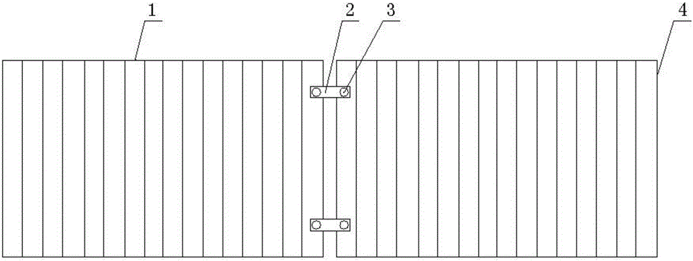
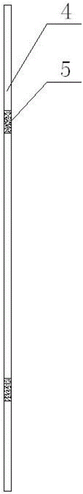
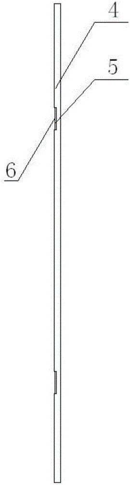
[0012] The present invention will be further described in detail below with reference to the accompanying drawings and specific embodiments. The following embodiments are only descriptive, not restrictive, and cannot limit the protection scope of the present invention.
[0013] A fixed piece resistance structure for welded mesh, the limit structure is used for two adjacent welded meshes 1 on the guardrail net, and the spokes 4 of the fixed piece 2 to be installed on the welded mesh are provided with a surface contact with the fixed piece. The wide surface is provided with a limiting groove 6 on the wide surface, the surface of the groove is provided with a pitted surface 5, and the wide surface is two, including an upper contact surface and a lower contact surface, which are arranged on the upper and lower surfaces of the spokes. It is the spoke on one side of the two adjacent welded mesh sheets, which is close to the other side of the welded mesh sheet, and is located at the side end of the welded mesh sheet.
[0014] The fixing part is embedded in the limit groove, and the side spokes of the two welded mesh sheets are pressed and then fastened by bolts 3.
[0015] Although the embodiments and drawings of the present invention are disclosed for illustrative purposes, those skilled in the art will appreciate that various substitutions, changes and modifications are possible without departing from the spirit and scope of the invention and the appended claims Therefore, the scope of the present invention is not limited to the contents disclosed in the embodiments and drawings.

PUM

no PUM

Description & Claims & Application Information

We can also present the details of the Description, Claims and Application information to help users get a comprehensive understanding of the technical details of the patent, such as background art, summary of invention, brief description of drawings, description of embodiments, and other original content. On the other hand, users can also determine the specific scope of protection of the technology through the list of claims; as well as understand the changes in the life cycle of the technology with the presentation of the patent timeline. Login to view more.

Similar technology patents

Pulling cord winder for venetian blind

InactiveUS20060175022A1increase friction
Owner:CHENG LI MING

Anti-skid device for automobile

InactiveCN103552427Aincrease frictionGood anti-skid effect
Owner:张治国

Looper

InactiveCN105603642AImprove cloth feeding efficiencyincrease friction
Owner:孝感华越机电科技有限公司

Tractor for magnetic levitation traffic installation routing inspection rescue

InactiveCN104139787Aincrease friction areaincrease friction
Owner:成都金和工贸有限公司

Classification and recommendation of technical efficacy words

  • increase friction

Medical closure device

InactiveUS20090234377A1increase friction
Owner:ST JUDE MEDICAL SYST

Expansion dowel

InactiveUS20080050195A1increase frictionwell control
Owner:HILTI AG

Electronic cicarette

InactiveUS20160262449A1increase frictionprevent their use
Owner:KIMREE HI TECH
Why Eureka
Try Eureka