
A multi-plane pressure-resistant structure

A pressure-resistant structure and multi-plane technology, applied in pressure vessels, ships, gas/liquid distribution and storage, etc., to achieve the effect of simple production process, excellent structural characteristics, and strong pressure resistance

Active Publication Date: 2017-11-14
HUAZHONG UNIV OF SCI & TECH
View PDF1 Cites 0 Cited by
  • Summary
  • Abstract
  • Description
  • Claims
  • Application Information

AI Technical Summary

Problems solved by technology

[0004] Aiming at the above defects or improvement needs of the prior art, the present invention provides a multi-plane pressure-resistant structure, in which, through the design of the respective setting methods of its key components and their mutual connection and cooperation, the spherical shape can be fully utilized accordingly. The two different characteristics of the curvature change of the structure and the folding change of the multi-planar cylinder can have both the excellent structural characteristics of the spherical shell and the cylindrical shell, and it is no longer necessary to separate the cylindrical shell and the cylindrical shell in the actual manufacturing process. A transition section is set between the hemispherical shells, thereby effectively avoiding defects such as the overall performance degradation of the multi-plane cylindrical shell structure caused by the existence of the transition section, so it is especially suitable for equipment such as submarines, aircraft or projectiles

Method used


Image

  • A multi-plane pressure-resistant structure
  • A multi-plane pressure-resistant structure
  • A multi-plane pressure-resistant structure

Examples


Embodiment Construction

[0031] In order to make the object, technical solution and advantages of the present invention clearer, the present invention will be further described in detail below in conjunction with the accompanying drawings and embodiments. It should be understood that the specific embodiments described here are only used to explain the present invention, not to limit the present invention. In addition, the technical features involved in the various embodiments of the present invention described below can be combined with each other as long as they do not constitute a conflict with each other.

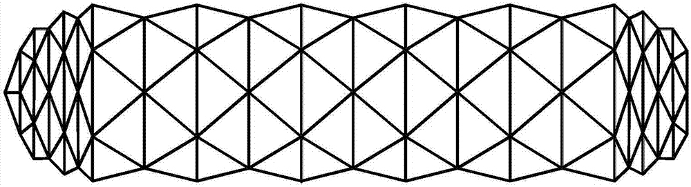
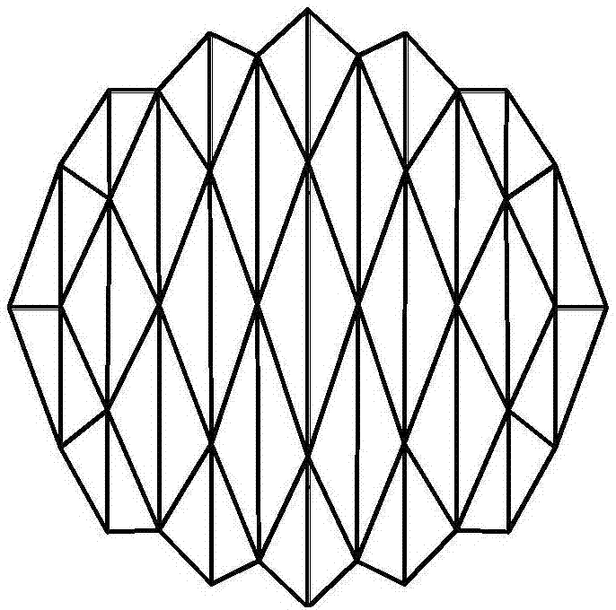
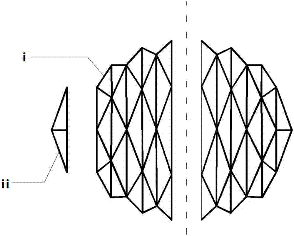
[0032] Figure 1(a) and (b) are the simulation diagrams of the multi-plane pressure-resistant structure; Figure 8 and Figure 9 It is the axial and radial cross-sectional view of the multi-planar cylindrical shell structure with sandwich structure after the smooth skin is set on the outer layer, Figure 10 It is the rendering of the simulated spacecraft and warhead model based on the multi-pla...


PUM


Abstract

The invention belongs to the field of pressure-resistant structures, and particularly relates to a multi-plane pressure-resistant structure. The multi-plane pressure-resistant structure is formed by a multi-plane cylinder and multi-plane semispherical shells at the two ends of the multi-plane cylinder jointly, or is directly formed by two identical multi-plane semispherical shells. The multi-plane semispherical shells are shaped like a spherical shell overall. The surface of each multi-plane semispherical shell is formed by mutually splicing a plurality of second basic plane plates, and a certain plane included angle exists between every two adjacent second basic plane plates. In the connecting positions of one multi-plane semispherical shell with the multi-plane cylinder / the other multi-plane semispherical shell, smooth curved line transition is not adopted between the basic plane plates. The multi-plane pressure-resistant structure guarantees the pressure resistance, lowers the influence of transition sections between the cylinder and the spherical shells on the mechanical characteristics of the whole multi-plane cylinder shell structure, and has the advantages of being high in pressure resistance, simple in production process, short in manufacturing period, easy to produce on a large scale and the like.

Description

technical field [0001] The invention belongs to the field of compression structures, and more specifically relates to a multi-plane pressure-resistant structure, which reduces the impact of the transition section between the cylinder and the spherical shell on the entire multi-plane cylindrical shell structure while ensuring the pressure-resistant performance. influence on the mechanical properties. Background technique [0002] For equipment that needs to withstand high external pressure during work, such as aircraft, submarines, bullets, etc., the structure of the cylindrical shell has a crucial impact on its compressive performance. In order to enhance the external pressure resistance of the shell structure, there are usually two methods, one is to thicken the existing structure to enhance its own structural characteristics, and the other is to modify the existing structure to achieve enhancement through structural advantages The purpose of structural mechanical properti...

Claims


Application Information

Patent Timeline
Patent Type & Authority Patents(China)
IPC IPC(8): B63B3/13
CPCF16J12/00F16J13/00
Inventor 赵耀袁华石宝雨胡昌成董宏宝储炜
Owner HUAZHONG UNIV OF SCI & TECH
Learn More