Combined Load Measuring Device

A technology of measuring device and combined load, applied in the direction of measuring device, instrument, scientific instrument, etc., can solve the problem of low measurement accuracy

Active Publication Date: 2019-08-23
无锡市海航电液伺服系统股份有限公司
View PDF8 Cites 0 Cited by
  • Summary
  • Abstract
  • Description
  • Claims
  • Application Information

AI Technical Summary

Problems solved by technology

[0003] In view of the above problems, the present invention provides a combined load measuring device, which can solve the problem of low measurement accuracy existing when a three-dimensional load sensor is used to detect a two-dimensional force combined load

Method used


Image

  • Combined Load Measuring Device
  • Combined Load Measuring Device
  • Combined Load Measuring Device

Examples


Embodiment 1

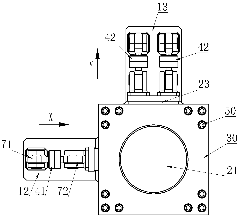
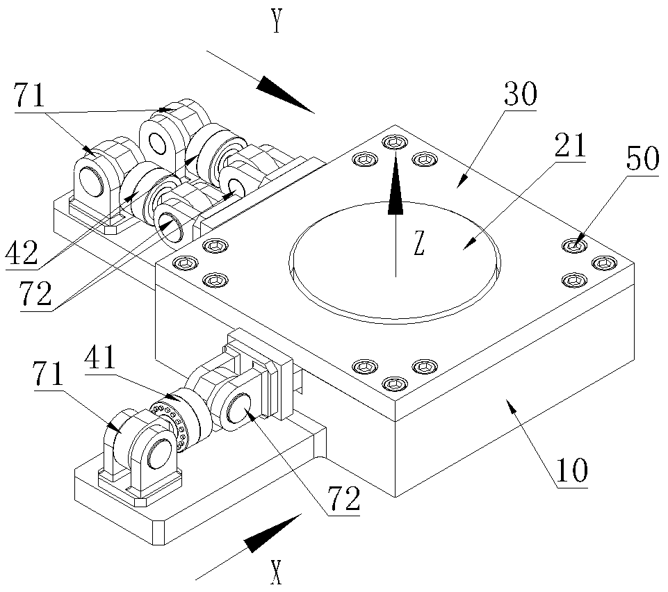
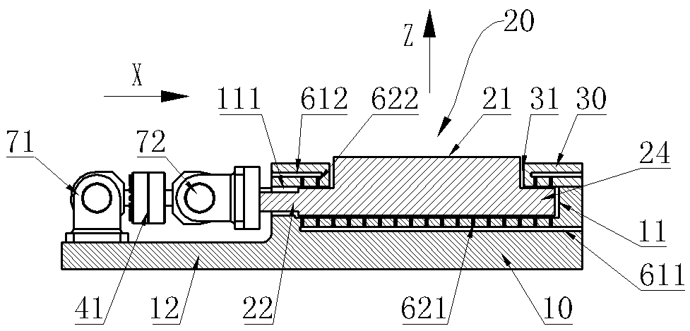
[0020] See Figure 1 ~ Figure 3 , which includes a base 10, a floating platform 20 and a cover plate 30, the base 10 is provided with an accommodating groove 11 with an open top, the cover plate 30 has a central cavity 31, the cover plate 30 is covered on the base of the 10 and is fixed by a set screw 50 The floating platform 20 is limited in the receiving groove 11. The floating platform 20 includes a bottom platform base 24 and a top boss 21 arranged concentrically. The top boss 21 passes upward through the central cavity 31 of the cover plate 30 so that the top surface of the boss 21 Exposed, a group of vertically adjacent horizontal sides and a vertical side at the bottom of the floating platform 20 are respectively provided with a horizontal extension 22 and a longitudinal extension 23, and a horizontal wall and a vertical extension of the accommodation groove 11 are vertically adjacent to each other. There are horizontal through grooves 111 and longitudinal through groov...

Embodiment 2

[0024] Embodiment 2 differs from Embodiment 1 only in the static pressure support structure, see Figure 4 , in the second embodiment, the static pressure support structure includes an upper high-pressure oil passage 613 and a lower high-pressure oil passage 614, and the upper high-pressure oil passage 613 and the lower high-pressure oil passage 614 are parallel to each other in the bottom platform base 24 of the floating platform 20, and the floating platform The top surface and the bottom surface of the bottom platform base 24 of 20 also have some high-pressure oil injection ports 623,624 which communicate with the upper high-pressure oil passage 613 and the lower high-pressure oil passage 614 respectively.

Embodiment 3

[0026] The difference between the third embodiment and the first and second embodiments is that the four corners of the base 10 are respectively provided with lug blocks 14, and the two transverse sides and two longitudinal sides of the bottom of the floating platform 20 are respectively provided with transverse extensions. Outlet 22, longitudinally extending end 23, the four lug blocks 14 are respectively connected with the first double ear seat 81 through the universal ball joint 73, and the transversely extending end 22 and longitudinally extending end 23 of the floating platform 20 are respectively The second double ear seat 82 is rotatably connected with the universal ball joint 74, the flange end of the load sensor 43 is connected with the second double ear seat 82, and the shaft hole end of the load sensor 43 is connected with the first double ear seat 81 through a stud 83. connection; the two-dimensional force combined load measuring device of this embodiment is adopted...


PUM


Abstract

The invention provides a combined load measuring device which can solve the problem that in the prior art, a three-dimensional load sensor is low in measurement precision when used for detecting two-dimensional force combined loads. The combined load measuring device comprises a base, a floating platform and a cover plate. A containing groove with the top opened is formed in the base. A central cavity is formed in the cover plate. The cover plate covers and is fixedly connected to the base and limits the floating platform within the containing groove. The floating platform is provided with a top boss, and the top boss upwards penetrates through the central cavity of the cover plate so that the top face of the boss can be exposed outside. The perpendicularly adjacent transverse lateral side and longitudinal lateral side of the bottom of the floating platform are provided with a transverse extending end and a longitudinal extending end respectively. The transverse extending end and the longitudinal extending end penetrate through the corresponding groove walls of the containing groove and are then connected with corresponding load sensors respectively. The groove bottom of the containing groove and the bottom of the cover plate are each provided with a static pressure supporting structure. Static pressure supporting is achieved between the floating platform and the groove bottom face of the containing groove and between the floating platform and the bottom face of the cover plate through the static pressure supporting structures respectively.

Description

technical field [0001] The invention relates to the technical field of load measurement, in particular to a combined load measurement device. Background technique [0002] At present, when the test piece is subjected to loads in the X, Y, and Z directions, traditional three-way load sensors are often used to measure the loads in the X and Y directions. However, due to the low measurement accuracy of the three-way load sensor, especially When the vertical load (that is, the Z-direction load) is large, for example, the Z-direction load borne by the building is much larger than the X-direction and Y-direction loads, so when the three-direction load sensor is used for detection, there will be loads in the three directions. There will be large interference between them, which will seriously affect the accuracy of X-direction and Y-direction load measurement. Contents of the invention [0003] In view of the above problems, the present invention provides a combined load measuri...

Claims


Application Information

Patent Timeline
Patent Type & Authority Patents(China)
IPC IPC(8): G01N3/04G01N3/06
CPCG01N3/04G01N3/06
Inventor 朱晓兵
Owner 无锡市海航电液伺服系统股份有限公司
Why Eureka
Try Eureka