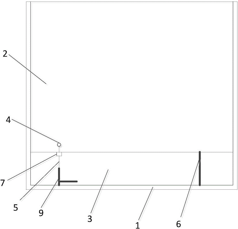
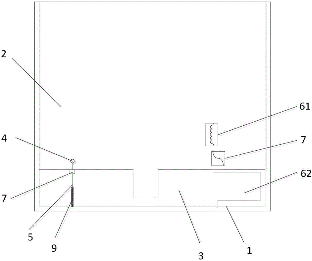
[0020] The embodiment of the present invention provides an antenna device and a terminal to solve the existing need to cut the metal frame or the metal back shell to realize the function of the antenna, which brings about the deterioration of product appearance consistency and reliability, and the increase in cost. problem.
[0021] In order to enable those skilled in the art to better understand the solutions of the present invention, the technical solutions in the embodiments of the present invention will be described clearly and completely with reference to the accompanying drawings in the embodiments of the present invention. Obviously, the described embodiments are only It is a part of the embodiments of the present invention, not all the embodiments. Based on the embodiments of the present invention, all other embodiments obtained by those of ordinary skill in the art without creative work shall fall within the protection scope of the present invention.
[0022] Detailed descriptions are given below.
[0023] The terms "first", "second", "third", "fourth", etc. (if any) in the description and claims of the present invention and the above-mentioned drawings are used to distinguish similar objects, and are not necessarily used Describe a specific order or sequence. It should be understood that the data used in this way can be interchanged under appropriate circumstances so that the embodiments described herein can be implemented in a sequence other than the content illustrated or described herein.
[0024] See figure 1 , figure 1 It is a diagram of an embodiment of the antenna device of the present invention. The antenna device may include a metal frame 1, a clearance area 3 is provided between one end of the metal frame and the circuit board 2 of the terminal, and a radio frequency module arranged on the circuit board A feed point 4 is connected to the feed point, a feed metal trace 5 is connected to the feed point, one end of the feed metal trace is connected to the metal frame, and one side of the clearance area is also provided with impedance The loading device 6 has two ends of the impedance loading device respectively connected to the circuit board and the metal frame.
[0025] It can be seen that by flexibly using a part of the metal frame as an antenna, and using an impedance loading device, the metal frame can be used as an antenna without any processing such as slitting and cutting. The impedance loading device can be used to adjust the loading impedance to facilitate the antenna The radio frequency module is connected with a feeding point, and the feeding metal trace connected to the feeding point feeds the metal frame, so as to realize the antenna of multiple communication frequency bands. Compared with the metal back shell or the metal frame, Can reduce costs, improve product reliability and appearance consistency.
[0026] Optional, see figure 2 , figure 2 It is another embodiment diagram of the antenna device according to the embodiment of the present invention. The impedance loading device includes a capacitor 62 and/or an inductor 61, and the capacitor and/or inductor and the metal frame form a resonant structure.
[0027] It is understandable that the function of the impedance loading device is mainly used to adjust the loading impedance to achieve impedance matching during antenna transmission. The impedance connection device can be composed of capacitors or inductors or capacitors plus inductors in three ways. The wiring conditions are adjusted adaptively.
[0028] Optionally, the capacitor and/or the inductance are lumped parameter capacitors and/or lumped parameter inductors.
[0029] Optionally, the capacitor and/or the inductance are distributed parameter capacitors and/or distributed parameter inductors.
[0030] It is understandable that for the impedance loading device, the capacitor can be a lumped parameter capacitor or a distributed parameter capacitor, and the inductance can be a lumped parameter inductor or a distributed parameter inductor. If the impedance loading device has both capacitance and inductance, the capacitance and inductance It can be lumped parameter type or distributed parameter type.
[0031] Optionally, the distributed parameter capacitor and/or the distributed parameter inductor are further connected to a radio frequency switch 7.
[0032] Wherein, the purpose of the radio frequency switch is to cooperate with the impedance loading device to achieve impedance matching in the communication process. The provision of the radio frequency switch can also improve the transmission efficiency, reduce the current consumption of the transmitting end, and improve the receiving sensitivity of the receiving end.
[0033] Optionally, a matching network 8 for tuning is also connected between the feeding metal trace and the feeding point.
[0034] Among them, the main function of the matching network is to tune the antenna to achieve the purpose of impedance matching.
[0035] Optionally, a metal branch 9 is further provided on the feeding metal trace.
[0036] Optionally, the metal branches include at least one of a linear type, a bent type, and a curved type.
[0037] It is understandable that the purpose of the metal branch is to generate resonances in different frequency bands, so that the antenna can work in more frequency bands, that is, it can realize the full frequency band of Long Term Evolution (LTE) or other such as WI-FI, The antenna performance of global positioning technology (GPS, Global Positioning System) and other communication frequency bands, in addition, the wiring form of the metal branches can be any wiring to make full use of the design space.
[0038] The antenna device of the embodiment of the present invention is described above, and the terminal of the embodiment of the present invention is described below, and the above-mentioned antenna device is installed on the terminal.
[0039] Optionally, the antenna device is located at the bottom of the terminal, and the metal frame is a bottom frame on the metal frame of the terminal.
[0040] Those skilled in the art can clearly understand that, for the convenience and conciseness of the description, the specific working process of the above-described system, device, and unit can refer to the corresponding process in the foregoing method embodiment, which will not be repeated here.
[0041] In the several embodiments provided in this application, it should be understood that the disclosed system, device, and method may be implemented in other ways. For example, the device embodiments described above are merely illustrative. For example, the division of the units is only a logical function division, and there may be other divisions in actual implementation, for example, multiple units or components can be combined or It can be integrated into another system, or some features can be ignored or not implemented. In addition, the displayed or discussed mutual coupling or direct coupling or communication connection may be indirect coupling or communication connection through some interfaces, devices or units, and may be in electrical, mechanical or other forms.
[0042] The units described as separate components may or may not be physically separated, and the components displayed as units may or may not be physical units, that is, they may be located in one place, or they may be distributed on multiple network units. Some or all of the units may be selected according to actual needs to achieve the objectives of the solutions of the embodiments.
[0043] In addition, the functional units in each embodiment of the present invention may be integrated into one processing unit, or each unit may exist alone physically, or two or more units may be integrated into one unit. The above-mentioned integrated unit can be realized in the form of hardware or software functional unit.
[0044] As mentioned above, the above embodiments are only used to illustrate the technical solutions of the present invention, but not to limit them; although the present invention has been described in detail with reference to the foregoing embodiments, those of ordinary skill in the art should understand that: The technical solutions recorded in the embodiments are modified, or some of the technical features are equivalently replaced; these modifications or replacements do not cause the essence of the corresponding technical solutions to deviate from the spirit and scope of the technical solutions of the embodiments of the present invention.