Hollow thin electric conduction link

A conductive slip ring and hollow technology, which is applied in the direction of circuits, current collectors, electrical components, etc., can solve the problems of restricting the functions of application equipment, restricting the continuous rotation function, and only rotating within 360 degrees.

Inactive Publication Date: 2016-11-16
沈阳凤天机器人科技有限公司
View PDF4 Cites 1 Cited by
  • Summary
  • Abstract
  • Description
  • Claims
  • Application Information

AI Technical Summary

Problems solved by technology

[0002] The known conductive slip rings are mostly structured with solid shafts, laminated collector rings and brushes, and there is no channel for increasing the number of wires in the axial direction, thus limiting the function of some application equipment.
For example, some robot end effectors mounted in

Method used


Image

  • Hollow thin electric conduction link

Examples


Embodiment Construction

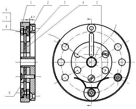
[0012] In the inner ring of the fixed ring (1) of the conductive slip ring, an insulating connecting piece (3) is arranged, and the connecting piece and the fixed ring (1) can rotate relatively and are constrained radially by the structure of the fixed ring (1); the insulating connecting piece (3) Two collector rings (4) fixedly connected with the moving ring (2) are installed at both ends, and the collector ring-connecting piece-collector ring-moving ring are connected and fixed in sequence with screws (9) , which forms the constraint of the fixed ring on the collector ring (4) and the moving ring (2) in the axial direction, and constitutes a relatively rotatable fixed ring and moving ring combination structure. The hollow hole and the long waist hole on the moving ring are namely Be the channel for the expansion wire.

[0013] On the fixed ring (1), fix and install the brush (5) which is in sliding contact with the collector ring (4) with screws (6), gaskets (7), and nuts (8...


PUM


Abstract

The invention relates to the technical field of electrical apparatuses and particularly provides a hollow thin electric conduction link. The traditional electric conduction link mostly has a solid shaft, collector rings and electric brushes are arranged in an axial overlapped mode, no channel for adding of wires exists in the axis direction, line connection between certain execution devices in need of serial connection and with relative rotary motion relies on external open wires, playing of the continuous rotary function of devices is limited, and the devices can only rotate within 360 DEG. In order to solve the problem of wire number application expansion of the electric conduction link, the invention provides a hollow and thin electric conduction link, and a certain number of wires can pass through the hollow channel. With a middle piece associated with a fixing ring and a moving ring, radial and axial constraints on the moving ring by the fixing ring are formed, an electric conduction link structure with the fixing ring and the moving ring capable of rotating relatively combined into a whole is formed, a hollow hole in the moving ring becomes the channel for expanding the wires, and the purpose of wire number series expansion can be realized.

Description

technical field [0001] The invention relates to the technical field of electrical appliances, in particular to provide a hollow thin conductive slip ring. Background technique [0002] Most of the known conductive slip rings are structured with a solid shaft, laminated collector rings and brushes, and there is no channel for increasing the number of wires in the axial direction, thus limiting the function of some application equipment. For example, some robot end effectors mounted in series that rotate continuously use conventional conductive slip rings, and then the line connection of the series-connected executive devices can only be connected through external open wires, which limits the continuous rotation of the executive device function so that it can only rotate within 360 degrees. Contents of the invention [0003] In order to solve the problem of expanding the number of wires of the conductive slip ring, the invention provides a hollow, thin conductive slip ring,...

Claims


Application Information

Patent Timeline
IPC IPC(8): H01R39/08
CPCH01R39/08
Inventor 张选琪
Owner 沈阳凤天机器人科技有限公司
Why Eureka
Try Eureka