Flapping rotor wing design method and microminiature flapping rotor wing designed according to the method

A design method and aircraft technology, applied to aircraft, helicopters, motor vehicles, etc., can solve the problems of difficult miniaturization, low lift and body weight, complex aircraft structure, etc., and achieve the effect of simple structure, light weight and small volume

Inactive Publication Date: 2009-07-29
BEIJING INSTITUTE OF TECHNOLOGYGY
View PDF0 Cites 43 Cited by
  • Summary
  • Abstract
  • Description
  • Claims
  • Application Information

AI Technical Summary

Problems solved by technology

[0006] The purpose of the present invention is to provide a rotorcraft with complex structure, low ratio of lift to body weight and difficulty in miniaturization due to the need ...

Method used


Image

  • Flapping rotor wing design method and microminiature flapping rotor wing designed according to the method
  • Flapping rotor wing design method and microminiature flapping rotor wing designed according to the method
  • Flapping rotor wing design method and microminiature flapping rotor wing designed according to the method

Examples


Embodiment 1

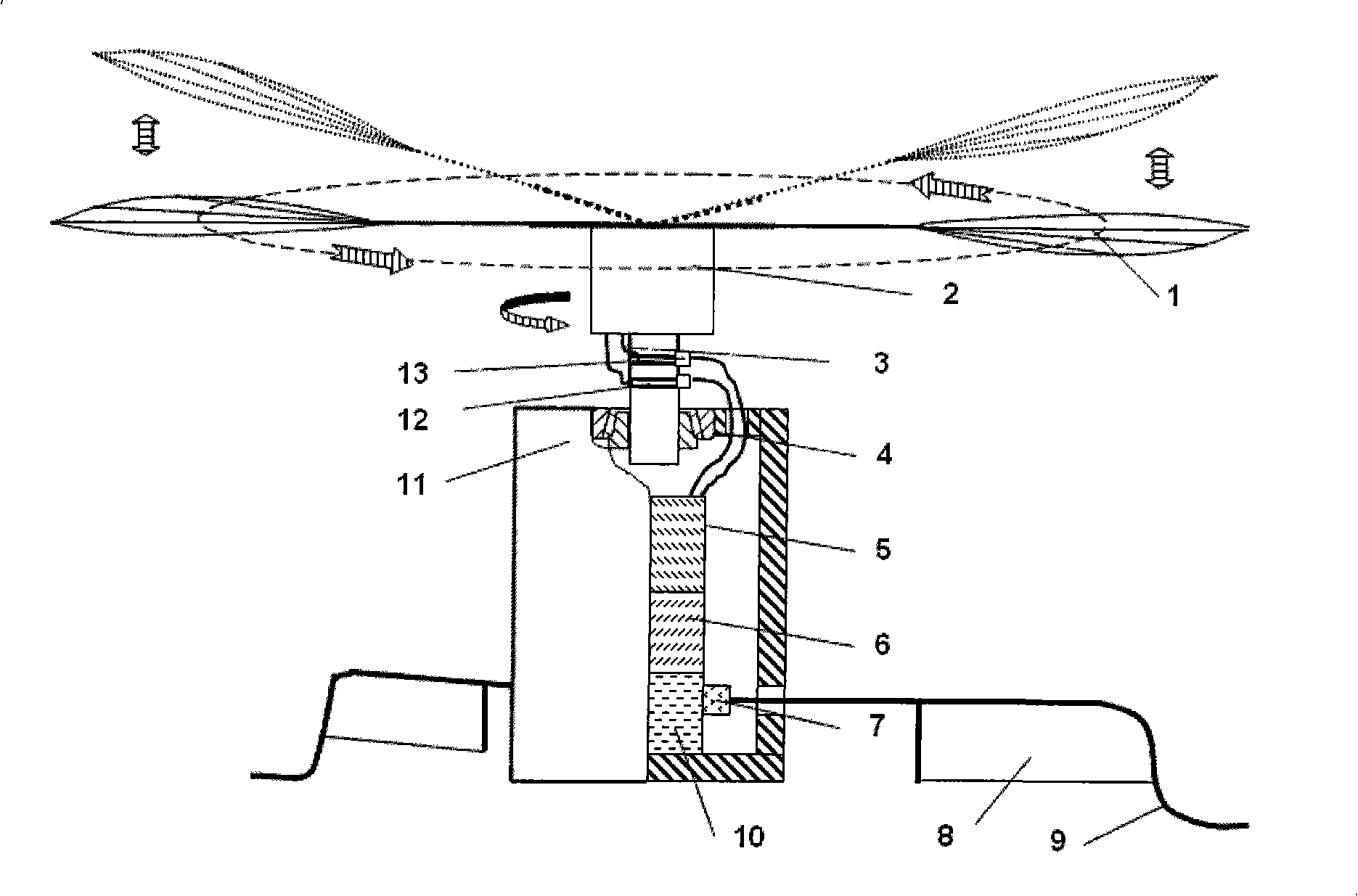
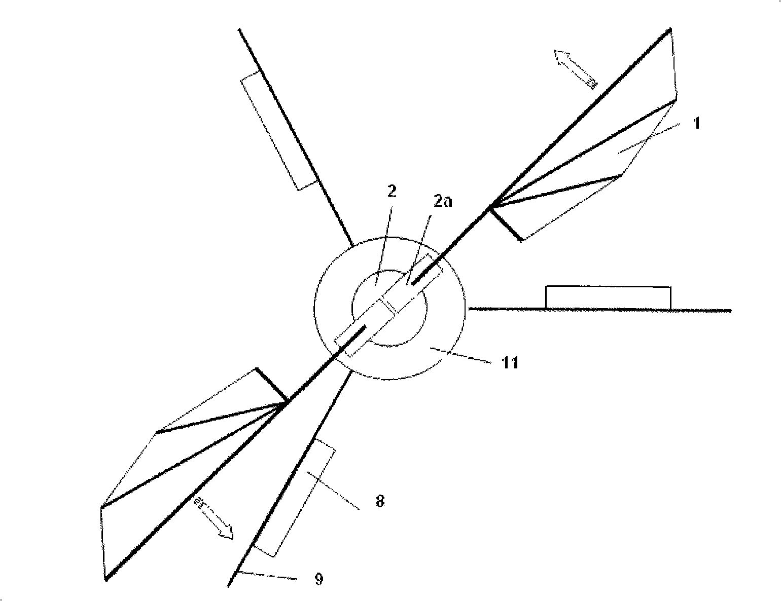
[0027] A micro flapping rotor aircraft of the present invention comprises a flapping wing 1, an electromagnetic drive mechanism 2, a connecting shaft 3 connecting the flapping wing and the body, a body shell 11, a control surface 8, an undercarriage 9, a power supply 5, and a controller 10 and electric steering gear 7.

[0028] The production steps of the flapping rotorcraft are as follows:

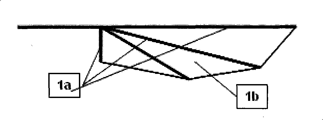
[0029] The first step is to make flapping wing 1. The polyvinyl chloride film used for ordinary packaging is selected as the material of the flapping wing surface, according to the attached image 3 The shown flapping wing shape trims the airfoil, and glues four reinforcing ribs 1a on the trimmed airfoil 1b, and the reinforcing ribs are carbon fiber composite materials.

[0030] The second step is to make the electromagnetic driving mechanism 2 . The present invention adopts "W" electromagnetic driving mechanism. First, two U-shaped soft irons are juxtaposed together, and the magnetic ...

Embodiment 2

[0036] A micro flapping rotor aircraft of the present invention comprises a flapping wing 1, an electromagnetic drive mechanism 2, a connecting shaft 3 connecting the flapping wing and the body, a body shell 11, a control surface 8, an undercarriage 9, a power supply 5, and a controller 10 and electric steering gear 7.

[0037] The first step is to make three flapping wings 1. The polyvinyl chloride film used for ordinary packaging is selected as the material of the flapping wing surface, according to the attached image 3 The shown flapping wing shape trims the airfoil, and glues four reinforcing ribs 1a on the trimmed airfoil 1b, and the reinforcing ribs are carbon fiber composite materials.

[0038] In the second step, in order to increase the aerodynamic efficiency of the airfoil, the embodiment of the present invention uses a "3W" electromagnetic drive mechanism to drive three flapping wings, such as Figure 5 As shown, the outer surface of three U-shaped soft irons rel...


PUM


Abstract

The invention provides a method for driving flapping wings to rotate by thrust produced by the flap of the flapping wings instead of driving by an electric motor, and the method combines with flapping wing and rotary wing technology. An aircraft designed by the method of the invention comprises the flapping wings, an electromagnetic driving mechanism, a connecting shaft, a roller bearing, a power supply, useful load, an electric steering engine, control surfaces, an undercarriage, a controller, an aircraft shell, a slip ring and an electric brush, wherein the electromagnetic driving mechanism drives a pair of flapping wings to flap up and down. The aircraft shell is connected with a rotary connecting shaft through the roller bearing, three control surfaces are evenly distributed at the lower part of the aircraft shell, and simultaneously the control surfaces have the function of the undercarriage of the aircraft. The flapping rotary wings of the invention have high pneumatic efficiency and can satisfy the mission and requirements of vertical takeoff and landing and hovering stopping of the aircraft. Simultaneously, the rotation of the flapping wings of the aircraft is a self-driven rotation, and the rotation is not offset by a torsion resisting mechanism which is added additionally. The aircraft has the advantages of simple design structure, light weight and high flight efficiency and is suitable for miniaturization aircraft design requirements.

Description

technical field [0001] The design of the invention belongs to the technical field of micro-aircraft, and in particular relates to a self-rotating aircraft combining flapping wing and rotor technology. Background technique [0002] In 1992, the US Defense Advanced Research Project Agency (Defense Advanced Research Project Agency, referred to as DARPA) first proposed the concept of Micro Air Vehicles (MicroAir Vehicles, referred to as MAV). The main feature of MAVs is their small size. The US DARPA’s requirements for MAVs are: wingspan and length less than 6 inches (152 mm), a total weight of about 80-150 grams, a payload of about 20 grams, and an endurance of 20 -60 minutes, the flight speed is 30-60 km / h, with real-time imaging, navigation and communication capabilities. MAV has extremely wide application prospects and use value, and has become a new research hotspot in the world today. [0003] Judging from the existing research situation, MAVs can be divided into three c...

Claims


Application Information

Patent Timeline
IPC IPC(8): B64C33/00B64C33/02
Inventor 郭士钧王正杰范宁军王正平吴炎烜
Owner BEIJING INSTITUTE OF TECHNOLOGYGY
Why Eureka
Try Eureka