Fixing mechanism for terminal strip of switch cabinet and meter room

A fixing mechanism and terminal fixing technology, applied in substation/switch layout details, substation/switchgear board/panel/desk, electrical components, etc., can solve problems such as unfavorable wiring installation, inconvenient, unsightly, etc., to achieve convenience The effect of wiring, easy maintenance, and aesthetic improvement

Inactive Publication Date: 2016-11-16
HEBEI ELECTRIC POWER EQUIP
View PDF4 Cites 3 Cited by
  • Summary
  • Abstract
  • Description
  • Claims
  • Application Information

AI Technical Summary

Problems solved by technology

In the prior art, when installing the terminals, it is necessary to install the terminals on the terminal block, and then directly fix the terminal block with the terminal blocks on the cabinet body, because the terminal block is directly fixed on the cabinet body. It cannot be rotated, and it has the following defects: a. The terminal block is fixed, which is not conducive to wiring installation; b. The terminal block is fixed at one position, and its wiring method and distance need to be designed and measured, which is very time-consuming; c. If you need to check the wiring , maintenance and other work, it is very inconvenient; d, the fixed structure in the instrument box is not beautiful, giving people a rigid impression

Method used


Image

  • Fixing mechanism for terminal strip of switch cabinet and meter room
  • Fixing mechanism for terminal strip of switch cabinet and meter room
  • Fixing mechanism for terminal strip of switch cabinet and meter room

Examples


Embodiment Construction

[0018] The present invention will be described in further detail below in conjunction with accompanying drawing and specific embodiment

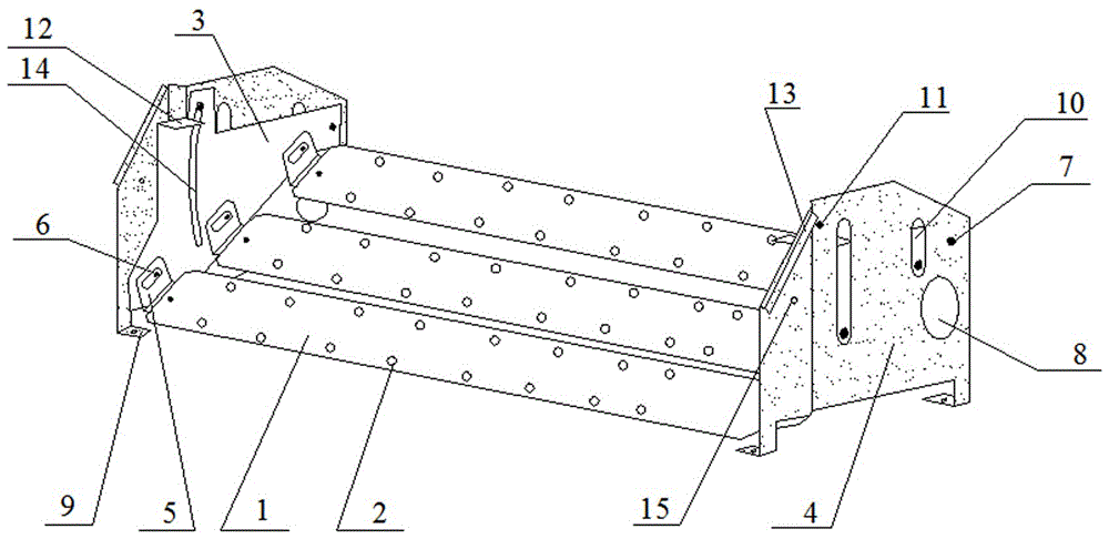
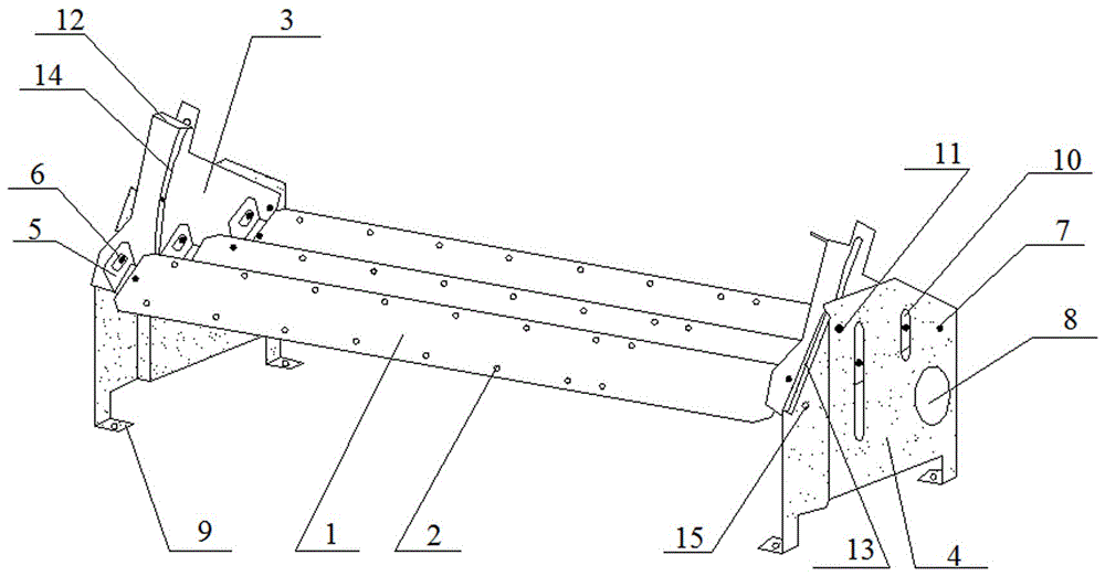
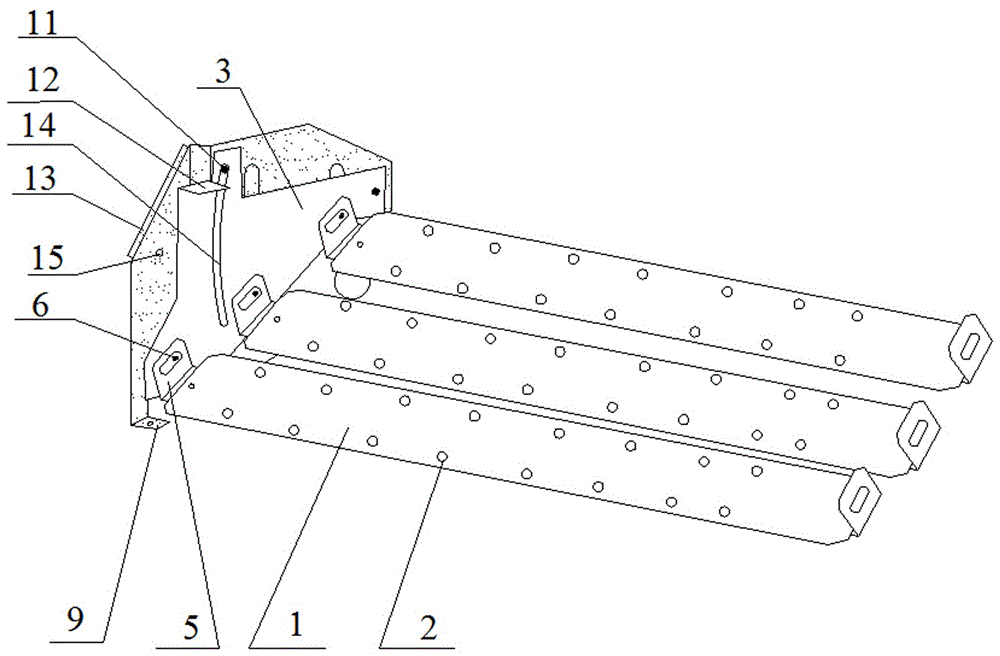
[0019] Such as figure 1 As shown, a terminal row fixing mechanism for the instrument room of a switchgear includes three rows of terminal fixing plates 1 composed of a front terminal fixing plate with a wire binding hole 2, a middle terminal fixing plate and a rear terminal fixing plate, located on the terminal fixing plate 1 Two ends and left and right symmetrical lifting brackets 3 and support plates 4, the support plate 4 is provided with a wire hole 8, the bottom is provided with a foot 9 with a mounting hole and an anti-scratch fold 13, and the support plate 4 is provided with The strip hole 10 for the screw end of the elastic bolt 6 to pass through, the support plate 4 has an outward expansion surface, that is, the cross section of the support plate 4 on the left side of the terminal fixing plate 1 is " " shape, the cross-section of ...


PUM


Abstract

The invention provides a fixing mechanism for a terminal strip of a switch cabinet and a meter room. The fixing mechanism comprises a terminal fixing plate, a lifting bracket and a supporting plate, wherein the terminal fixing plate is provided with a wiring hole; the lifting bracket and the supporting plate are located at the two ends of the terminal fixing plate and are symmetrical to each other on left and right sides; the terminal fixing plate is rotatably connected with the lifting bracket through a rotating bracket and a fastening bolt; the lifting bracket is rotatably connected with the supporting plate through a rotating bolt; a wiring hole is formed in the supporting plate; a supporting leg with a mounting hole is arranged at the bottom of the supporting plate; a bar-shaped hole through which a screw rod end of the fastening bolt can penetrate is formed on the supporting plate. The fixing mechanism provided by the invention has the advantages of reasonable design, simplicity in operation, capability of realizing up-and-down movement and overturning of the terminal strip, extreme convenience in terminal wiring and convenience in maintenance. The wires can be all arranged under the mechanism, so that the design and measuring time can be saved and the working efficiency is increased.

Description

technical field [0001] The invention belongs to the field of electric equipment, and in particular relates to a terminal row fixing mechanism for an instrument room of a switch cabinet. Background technique [0002] The main function of switchgear is to switch, control and protect electrical equipment during the process of power generation, transmission, distribution and power conversion in the power system. The components in the switch cabinet are mainly composed of circuit breakers, disconnectors, load switches, operating mechanisms, transformers and various protection devices. Switch cabinets are mainly used in various occasions such as power plants, substations, petrochemicals, metallurgical steel rolling, light industry textiles, factories and mines, residential quarters, and high-rise buildings. In the switch cabinet, secondary components such as fuses and terminals are generally installed inside the instrument room. In the prior art, when installing the terminals, i...

Claims


Application Information

Patent Timeline
Patent Type & Authority Applications(China)
IPC IPC(8): H02B1/00H02B1/015
CPCH02B1/00H02B1/015
Inventor 赵乘康虞忠新郝雪楠张腾朱丹周伟刘欣慧刘海晨
Owner HEBEI ELECTRIC POWER EQUIP
Why Eureka
Try Eureka