
Double-line intelligent LED dimming power supply

A technology of dimming power supply and LED lamp, applied in the direction of light source, electric light source, electroluminescent light source, etc., to achieve the effect of uniform lighting brightness, prolong life and reduce the probability of failure

Inactive Publication Date: 2016-11-16
胡志强
View PDF7 Cites 2 Cited by
  • Summary
  • Abstract
  • Description
  • Claims
  • Application Information

AI Technical Summary

Problems solved by technology

[0003] The purpose of the present invention is to provide a two-wire LED intelligent dimming power supply, which only uses the live and neutral wires for power supply, and does not require additional dimming signal lines, and specifically solves the technical problem of uniformly adjusting the brightness of each light source on the LED lamp.

Method used


Image

  • Double-line intelligent LED dimming power supply
  • Double-line intelligent LED dimming power supply
  • Double-line intelligent LED dimming power supply

Examples


Embodiment Construction

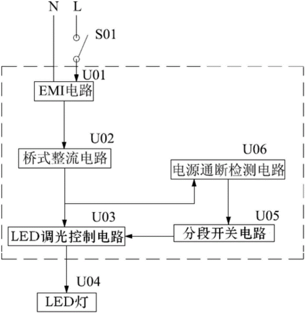
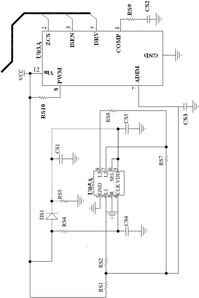
[0023] Such as figure 2 As shown, the intelligent dimming ballast for fluorescent lamps of the present invention includes a segmented switch circuit U05, a power on-off detection circuit U06, the input end of the power on-off detection circuit U06 is connected to the working power supply VCC of the LED dimming control circuit, and the output end is connected to The input end of the segment switch circuit U05 and the output end of the segment switch circuit U05 are connected to the dimming analog potential input end of the LED dimming control circuit. The power supply on-off detection circuit U06 is used to detect the on / off state of the working power of the LED dimming control circuit inside the power supply, and transmit the state signal to the sub-section switch circuit U05. The subsection switch circuit U05 selects different load circuits according to the on / off state of the working power supply of the LED dimming control circuit and converts it into an analog dimming sign...


PUM


Abstract

The invention provides a double-line intelligent LED dimming power supply and relates to a power supply. The double-line intelligent LED dimming power supply detects instant connection and disconnection of a commercial power switch and adjusts the brightness of an LED lamp through an LED dimming control circuit. The double-line intelligent LED dimming power supply comprises a section switch circuit connected with an LED dimming integrated control circuit, and a power on-off detection circuit connected with the section switch circuit. The power on-off detection circuit is used for detecting on / off state of a working power supply of the LED dimming integrated control circuit and sending the state to the section switch circuit; and the section switch circuit selects different load circuits and connects the circuits to an analog dimming signal input end of the LED dimming integrated control circuit according to the on / off state of the working power supply to realize dimming of the LED lamp. Dimming of various LED lamps can be realized directly by utilizing an instantaneous switch to control the on / off state of a commercial power AC power without increasing extra light modulation signal lines.

Description

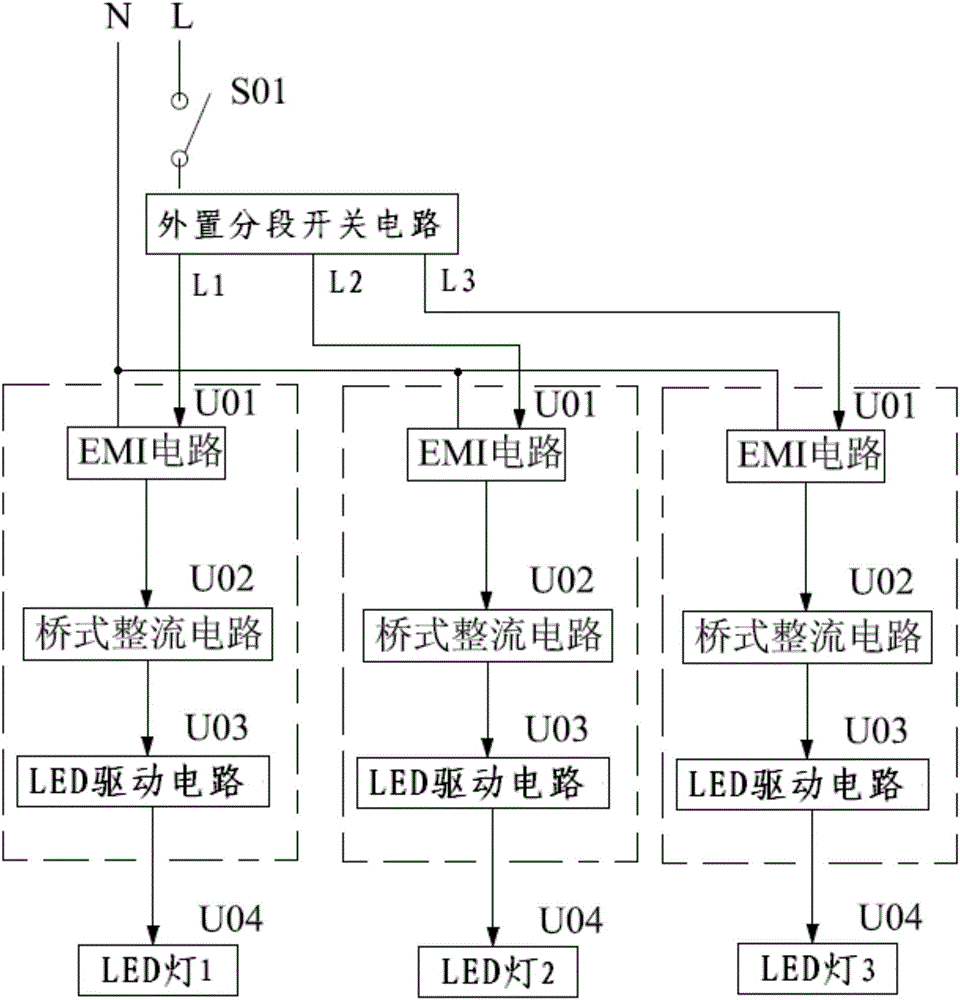
technical field [0001] The invention relates to an LED power supply, in particular to an LED power supply for adjusting the brightness of a light source. Background technique [0002] Such as figure 1 As shown, LED lamps are generally installed with a common LED power supply, which is connected to the mains AC power supply through the power switch S01. The power supply mainly includes the EMI circuit U01, the bridge rectifier circuit U02, and then the LED lamp U04 is lit through the LED drive circuit U03. . At present, the general-purpose multi-stage switch lamps on the market are generally equipped with 3 to 4 LED lamps with ordinary power supply. The external multi-stage switch circuit of the LED power supply controls the on-off of the relay to control the switch of the LED power supply, so that some lights are on and individual lights are on. The purpose of reducing the brightness of lamps and lanterns to save electricity. When adjusting the brightness of lamps with ma...

Claims


Application Information

Patent Timeline
IPC IPC(8): H05B33/08H05B44/00H05B45/10
CPCH05B45/37Y02B20/30
Inventor 胡志强
Owner 胡志强
Learn More