
A CO2 laser cutting power control method and system

A power control and laser cutting technology, applied in laser welding equipment, manufacturing tools, welding equipment, etc., can solve problems such as insufficient and inability to meet the process requirements of cutting workpiece ablation uniformity

Active Publication Date: 2018-04-24
CHENGDU FUYU TECH
View PDF5 Cites 0 Cited by
  • Summary
  • Abstract
  • Description
  • Claims
  • Application Information

AI Technical Summary

Problems solved by technology

The biggest disadvantage of this solution is that in a cutting movement, the power of the CO2 laser tube is a constant value, while the speed of the cutting path is constantly changing, which leads to a serious laser ablation of the workpiece material at places with low speed, while Where the speed is high, the degree of laser ablation of the workpiece may not be sufficient to meet the process requirements of cutting workpiece ablation uniformity

Method used


Image

  • A CO2 laser cutting power control method and system
  • A CO2 laser cutting power control method and system
  • A CO2 laser cutting power control method and system

Examples


Embodiment 1

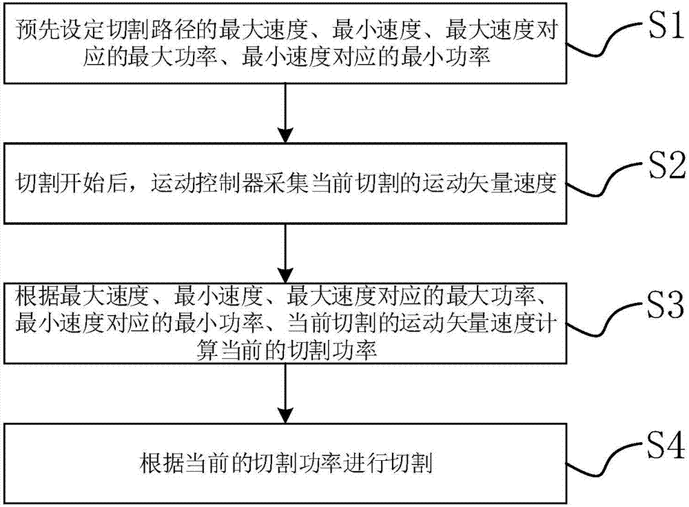
[0033] figure 1 It is a CO2 laser cutting power control method flow chart of the present invention, comprising the following steps,

[0034] S1. Preset the maximum speed, minimum speed, maximum power corresponding to the maximum speed, and minimum power corresponding to the minimum speed of the cutting path in advance;

[0035] S2. After the cutting starts, the motion controller collects the motion vector speed of the current cutting;

[0036] S3. Calculate the current cutting power according to the maximum speed, the minimum speed, the maximum power corresponding to the maximum speed, the minimum power corresponding to the minimum speed, and the current cutting motion vector speed;

[0037] S4. Cutting is performed according to the current cutting power.

[0038] Generally, in a cutting process, the cutting program is pre-designed according to the drawings. Since the speed of the cutting path may be constantly changing during the cutting process, however, the cutting speed ...


PUM


Abstract

The invention discloses a CO2 laser cutting power control method. The CO2 laser cutting power control method comprises the following steps that S1, the maximum speed, the minimum speed, the maximum power corresponding to the maximum speed and the minimum power corresponding to the minimum speed of a cutting path are preset; S2, after cutting is started, a motion controller collects the current cutting motion vector speed; S3, the current cutting power is calculated according to the maximum speed, the minimum speed, the maximum power corresponding to the maximum speed, the minimum power corresponding to the minimum speed and the current cutting motion vector speed; and S4, cutting is conducted according to the current cutting power. According to the CO2 laser cutting power control method, the cutting power of a laser tube can be precisely controlled in real time, and thus the process requirement for the ablation uniformity of the cut workpiece can also be met when the cutting speed is changed.

Description

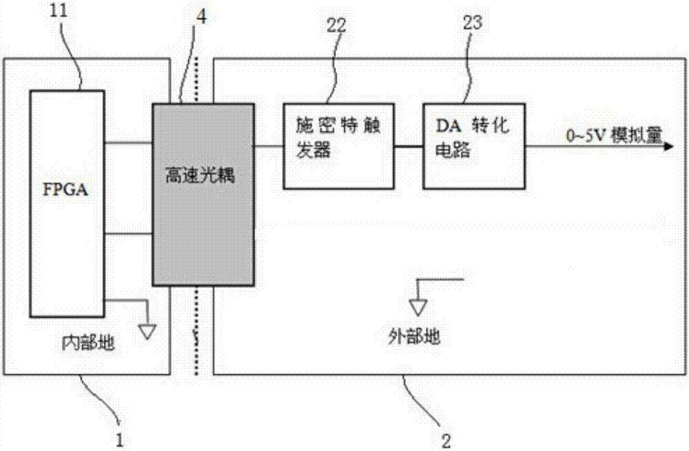
technical field [0001] The invention relates to the field of laser cutting, in particular to a CO2 laser cutting power control method and system. Background technique [0002] The CO2 laser cutting control system uses a focused high-power laser beam to irradiate the workpiece, so that the irradiated material is rapidly melted or ablated, and at the same time, the desired graphic shape is processed on the workpiece by setting a specific trajectory. The power of the CO2 laser tube is controlled by the CO2 laser, and the motion controller controls the output power of the CO2 laser tube by controlling the CO2 laser. Usually, the interface used by CO2 to control the laser power is an analog quantity (0-5V). So as long as the motion controller outputs an analog value (0~5V) to the CO2 laser, the power of the CO2 laser tube can be indirectly controlled. [0003] The existing solution is mainly to output a voltage of 0-5V to the CO2 laser by externally connecting a variable resisto...

Claims


Application Information

Patent Timeline
Patent Type & Authority Patents(China)
IPC IPC(8): B23K26/38B23K26/70
CPCB23K26/38B23K26/702
Inventor 谭平曹志明周维唐星黄俊豪
Owner CHENGDU FUYU TECH
Learn More