Automatic bolt locking machine
A bolt machine and automatic locking technology, applied in metal processing, metal processing equipment, manufacturing tools, etc., can solve the problems of large production line area and low production efficiency.
- Summary
- Abstract
- Description
- Claims
- Application Information
AI Technical Summary
Problems solved by technology
Method used
Image

Examples
Embodiment Construction
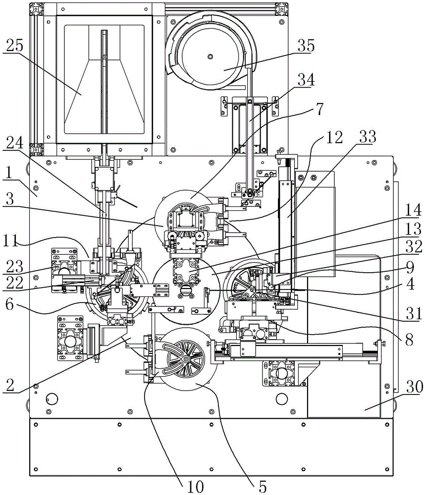
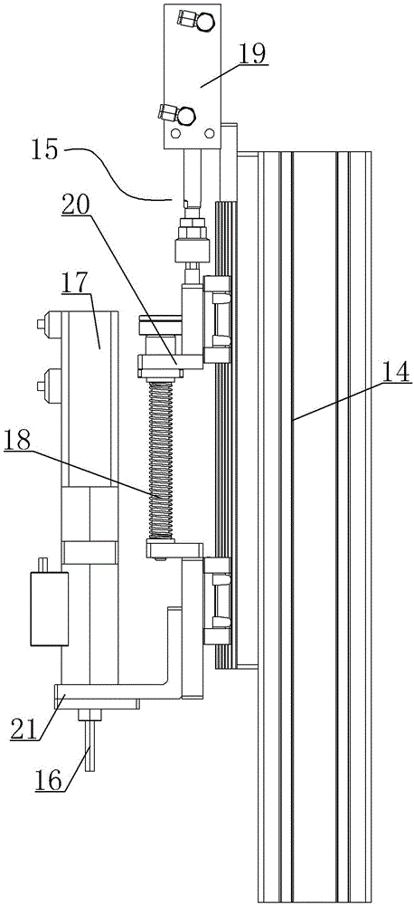
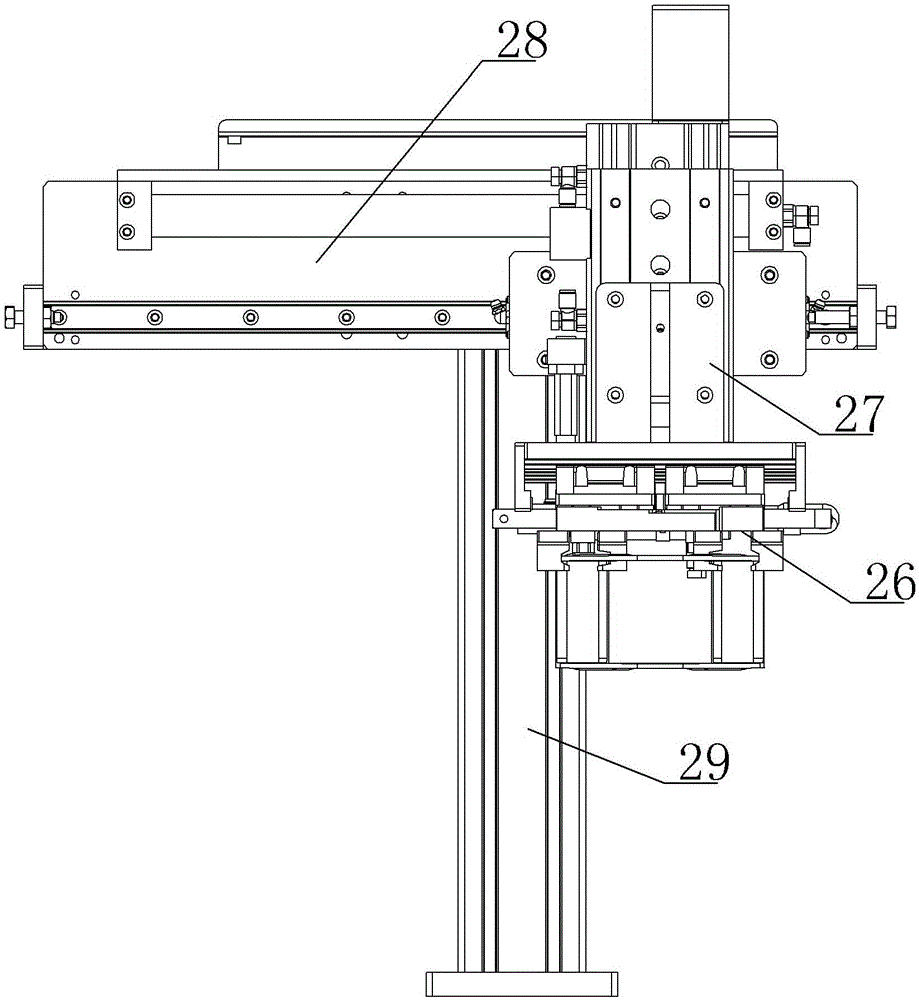
[0018] A kind of automatic locking bolt machine, see Figure 1 ~ Figure 2 : It includes a frame 1, the upper center of the frame 1 is provided with a closed circular track 2, four clamp structures 3 are evenly distributed on the circular track 2, and the bottoms of the four clamp structures 3 are respectively embedded in the circular The corresponding movable components on the track 2, the rotation direction of the circular track 2 is sequentially provided with the first station 4, the second station 5, the third station 6, and the fourth station 7, and the four fixture structures 3 correspondingly stay in the Corresponding station positions, the first station 4 is specifically the finished product blanking station 8 and the nut loading station 9, and the finished product blanking station 8 is arranged on one side of the fixture structure 3 staying at the first station 4, The nut feeding station 9 is arranged on the other side of the fixture structure 3 that stays at the first...
PUM
 Abstract
Description
Claims
Application Information
 - R&D
- Intellectual Property
- Life Sciences
- Materials
- Tech Scout
- Unparalleled Data Quality
- Higher Quality Content
- 60% Fewer Hallucinations
Browse by: Latest US Patents, China's latest patents, Technical Efficacy Thesaurus, Application Domain, Technology Topic, Popular Technical Reports.
© 2025 PatSnap. All rights reserved.Legal|Privacy policy|Modern Slavery Act Transparency Statement|Sitemap|About US| Contact US: help@patsnap.com