Turning plate type bidirectional sand discharging and removing device of track sand removing vehicle for both roads and railways

A road-rail dual-purpose, flap-type technology, applied in track cleaning, cleaning methods, construction, etc., can solve the problems of worn-out railway infrastructure, non-functioning, major traffic accidents, etc.

Active Publication Date: 2016-11-23
SHIJIAZHUANG TIEDAO UNIV
View PDF5 Cites 4 Cited by
  • Summary
  • Abstract
  • Description
  • Claims
  • Application Information

AI Technical Summary

Problems solved by technology

On the one hand, the wind and sand accumulate and hinder the railway equipment so that it cannot work normally, on the other hand, the railway infrastructure has been worn down for many years
Increased the risk of train derailment, causing major traffic accidents, resulting in delay or suspension
It has brought many troubles to the normal operation of the railway

Method used


Image

  • Turning plate type bidirectional sand discharging and removing device of track sand removing vehicle for both roads and railways
  • Turning plate type bidirectional sand discharging and removing device of track sand removing vehicle for both roads and railways
  • Turning plate type bidirectional sand discharging and removing device of track sand removing vehicle for both roads and railways

Examples


Embodiment 1

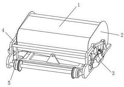
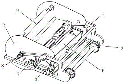
[0027] Embodiment one: if Figure 1-2 As shown, the present invention discloses a flip-type two-way sand removal device for a road-rail dual-purpose rail sand removal vehicle, including a frame 4, a sand collection part, a flip-type sand discharge part and a guide part, and the frame 4 is used for For carrying and connecting the driving device, the sand collection part is located at the front end of the frame 4, the flip-type sand discharge part is located behind the sand collection part and is used to accept the accumulated sand transported by the sand collection part, and the guide part is located at the frame 4 rear end, the frame structure of this embodiment is shown in the attached Image 6 , which is a symmetrically installed frame structure, which is mainly used to install auxiliary structures and connect the driving device when in use. The driving device can be used in conjunction with the applicant's previously applied invention patent "Rotary and Railway Dual-purpose...

Embodiment 2

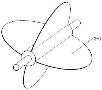
[0031] Embodiment two: the difference between the present embodiment and embodiment 1 is that the structure of the sand discharge part is different (see the attached Figure 7-10 ), the sand guide flap in this embodiment is a sand guide plate 10, the two sides of the middle part of the sand guide plate 10 are connected with the support by means of a rotating shaft, the two sides of the sand guide plate 10 are provided with upwardly protruding edges, and the two sides of the sand guide plate 10 Two upside-down triangular baffles 11 are respectively arranged on the upper side, and the top corners of the triangular baffles 11 are fixedly connected to the support, and the top edge of the triangular baffle 11 located on the inner side is close to the output end of the sand collecting part, and the sand blowing part 3 includes Sand blowing support, sand blowing wheel 3-1, sand blowing motor 7, sand blowing guide groove 3-2 and sand holding tank (see attached Figure 12 ), the sand h...


PUM


Abstract

The invention discloses a turning plate type bidirectional sand discharging and removing device of a track sand removing vehicle for both roads and railways. The turning plate type bidirectional sand discharging and removing device of the track sand removing vehicle for both roads and railways comprises a machine frame, a sand collecting portion, a turning plate type sand discharging portion and a guide portion, wherein the machine frame is used for being connected with a driving device; the sand collecting portion is located at the front end of the machine frame; the turning plate type sand discharging portion is located at the back of the sand collecting portion and used for receiving accumulated sand conveyed by the sand collecting portion; the guide portion is located at the rear end of the machine frame; the turning plate type sand discharging portion comprises a sand guide turning plate and sand lifting portions arranged on two sides of the machine frame; the middle of the sand guide turning plate is installed with the assistance of a support installed in the middle of the machine frame, the two sides of the sand guide turning plate are installed on the inner side of the support with the assistance of a rotary shaft, and outlets in two ends of the sand guide turning plate are located over the sand lifting portions on two sides of the machine frame; the sand collecting portion conveys the accumulated sand in an area to be cleaned into the sand discharging portion; the sand discharging portion is of a turning plate type structure, and according to the turning plate type structure, the output sides can be adjusted as needed; and the different output sides correspond to the sand lifting portions on different sides, free selection of the sand discharging direction can be realized, and adaptability is higher.

Description

technical field [0001] The invention relates to the technical field of railway sand removal, in particular to a flap-type two-way sand removal device for a road-rail dual-purpose track sand removal vehicle. Background technique [0002] Due to the impact of climate and environmental factors in Northwest my country, wind erosion of traffic lines has attracted more and more attention. According to my country's plan to expand the coverage of the western road network, there are about 20 newly-built railway sections in the wind erosion area, and the impact of traffic construction on soil wind erosion and the impact of wind erosion on engineering have been paid more and more attention. Even so, in areas with severe wind and sand, it often causes delays, delays and even rollovers of trains. [0003] The harm of wind and sand to the railway has also been paid more and more attention by people. On the one hand, the wind and sand accumulate and hinder the railway equipment so that i...

Claims


Application Information

Patent Timeline
Patent Type & Authority Applications(China)
IPC IPC(8): E01H8/12
CPCE01H8/12
Inventor 吴文江郑明军李张永李晨阳胡庆江王振兴郭斌
Owner SHIJIAZHUANG TIEDAO UNIV
Why Eureka
Try Eureka