Pipeline performance detection device

A detection device and pipeline performance technology, applied in the direction of measuring devices, material analysis through optical means, instruments, etc., can solve the problems of deviation of the detection results of the detection device, internal detection of the detection device pipeline, and the inability to locate the detection device. Convenience, easy installation and disassembly, simple structure

Inactive Publication Date: 2016-11-23
南京通用化工设备技术研究院有限公司
View PDF10 Cites 5 Cited by
  • Summary
  • Abstract
  • Description
  • Claims
  • Application Information

AI Technical Summary

Problems solved by technology

[0002] For pipeline detection in the chemical industry, due to the particularity of the internal structure of the pipeline, ordinary detection devices cannot detect the inside of the pipeline, and the interior of the pipeline is generally a circular structure, and the detection device cannot be fixed inside the pipeline, resulting in detection The detection result of the device deviates, and due to the problem that the detection device cannot be positioned, the traditional detection device cannot detect one section or one section inside the pipeline. The probe of the device is displaced and cannot be detected, and the detection accuracy is greatly reduced

Method used


Image

  • Pipeline performance detection device
  • Pipeline performance detection device

Examples


Embodiment 1

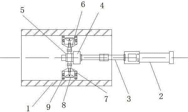
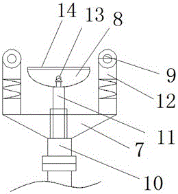
[0014] Embodiment 1: as figure 1 and 2 A pipeline performance detection device is shown, the detection device includes a hand-held rod 2, a connecting rod 3 and a detection end, the hand-held rod 2 is connected to the detection end through the connection rod 3, and the detection end is controlled by the base 4. Composed of an electric rotating shaft 5 and a detection bracket 6, the electric rotating shaft 5 is movably installed on the base 4, one end of the detection bracket 6 is connected to the electric rotating shaft 5 through a telescopic rod 10, the other end of the detection bracket One end is provided with an arc-shaped detection head 7, and the outside of the detection head 7 is provided with a plurality of transmission rollers 8 with elastic support rods 12. The inside of the detection head 7 is provided with an arc-shaped elastic sealing sleeve 8, and the elastic sealing sleeve 8 The inside is provided with a detection light source 13 and a signal sensor, the outsid...

Embodiment 2

[0015] Embodiment 2: as figure 1 and 2 As shown, the two ends of the connecting rod 3 are provided with flexible connecting ends, and the connecting rod 3 is movably installed between the hand-held rod 2 and the base 4; the connecting rod 3 is a detachable structure, according to the actual length of the pipeline 1 and the Shape, choose the connecting rod 3 of different specifications, the scope of application is wide, and the installation and dismounting operation of device is convenient at the same time.

Embodiment 3

[0016] Embodiment 3: as figure 1 and 2 As shown, the connecting rod 3 is an elastic connecting rod that can be bent into any shape; since the pipe 1 itself cannot be all linear, when there is a corner in the pipe 1, the bendable connecting rod 3 makes the detection end The head can move normally in the elbow 1 to meet different detection requirements.


PUM


Abstract

The invention discloses a pipeline performance detection device which comprises a hand lever, a joint lever and a detection end. The hand lever is connected to the detection end through the joint lever, the detection end is formed by a base, an electric rotating shaft and a detection support, the electric rotating shaft is movably mounted on the base, one end of the detection support is connected to the electric rotating shaft through a telescopic rod while the other end is provided with a cambered detection head, a plurality of transmission rollers with electric support bars are arranged on the outer side of the detection head, a circular elastic seal cartridge is arranged inside the detection head, a detection light source and a signal sensor are arranged inside the elastic seal cartridge, and the outer side of the elastic seal cartridge is connected to the detection head through a secondary telescopic rod. By the arrangement, a traditional detection device is modified, so that requirements of chemical enterprises on internal detection of various shapes or specifications of pipelines can be met, detection points inside the pipelines are positioned precisely and connected stably without skewing, and detection precision is high.

Description

technical field [0001] The invention relates to the field of pipeline testing equipment, in particular to a multifunctional pipeline performance testing device. Background technique [0002] For pipeline detection in the chemical industry, due to the particularity of the internal structure of the pipeline, ordinary detection devices cannot detect the inside of the pipeline, and the interior of the pipeline is generally a circular structure, and the detection device cannot be fixed inside the pipeline, resulting in detection The detection result of the device deviates, and due to the problem that the detection device cannot be positioned, the traditional detection device cannot detect one section or one section inside the pipeline. The probe of the device is displaced and cannot be detected, and the detection accuracy is greatly reduced. Contents of the invention [0003] In view of the above existing problems, the purpose of the present invention is to provide a pipeline ...

Claims


Application Information

Patent Timeline
Patent Type & Authority Applications(China)
IPC IPC(8): G01N21/01G01N21/954
CPCG01N21/01G01N21/954
Inventor 胡家富缪斌李浩聂小科
Owner 南京通用化工设备技术研究院有限公司
Why Eureka
Try Eureka