Mobile terminal charging device and mobile terminal

A mobile terminal and charging device technology, applied in circuit devices, battery circuit devices, charging/discharging current/voltage regulation, etc., can solve the problems of easy occurrence of electric shock and poor high-voltage safety, so as to improve high-voltage safety and shorten the charging path. Effect

Inactive Publication Date: 2016-11-23
GUANGDONG OPPO MOBILE TELECOMM CORP LTD
View PDF6 Cites 0 Cited by
  • Summary
  • Abstract
  • Description
  • Claims
  • Application Information

AI Technical Summary

Problems solved by technology

In this case, the high voltage passes from the small board to the main board through the flexible circuit board FPC, and then passes through the flexible circuit board FPC to the BTB board-to-board connector at the other end, and then charges the battery. The long charging path has high voltage. In the process of maintenance, the risk of electric shock is easy to occur, and the safety of high voltage is poor

Method used


Image

  • Mobile terminal charging device and mobile terminal

Examples


Embodiment Construction

[0016] Embodiments of the present invention are described in detail below, examples of which are shown in the drawings, wherein the same or similar reference numerals designate the same or similar elements or elements having the same or similar functions throughout. The embodiments described below by referring to the figures are exemplary and are intended to explain the present invention and should not be construed as limiting the present invention.

[0017] The mobile terminal charging device and the mobile terminal according to the embodiments of the present invention will be described below with reference to the accompanying drawings.

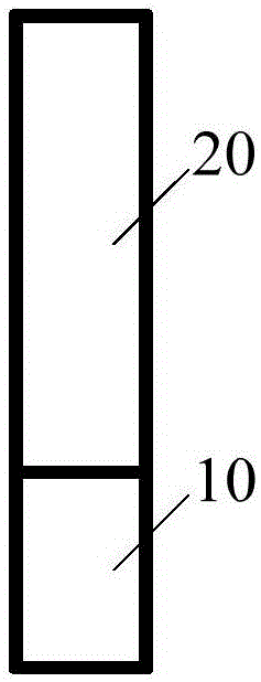
[0018] figure 1 It is a schematic structural diagram of a charging device for a mobile terminal according to an embodiment of the present invention.

[0019] It should be noted that the mobile terminal in the embodiment of the present invention may include a mobile phone, a tablet computer, and the like.

[0020] Such as figure 1 As shown...


PUM


Abstract

The invention discloses a mobile terminal charging device and a mobile terminal, wherein the charging device comprises a connecting seat used for inputting a charging voltage; a charging circuit located at the rear end of the connecting seat, and used for charging the cell of the mobile terminal according to the inputted charging voltage. The mobile terminal charging device can substantially shorten a charging path, and thereby improve the high voltage safety in mobile terminal charging.

Description

technical field [0001] The invention relates to the technical field of mobile terminals, in particular to a charging device for a mobile terminal and a mobile terminal. Background technique [0002] At present, most of the USB connection sockets of mobile terminals are designed on small boards. The flash charging voltage is supplied to the main board through the USB connection socket and the long flexible circuit board FPC. Charge. In this case, the high voltage passes from the small board to the main board through the flexible circuit board FPC, and then passes through the flexible circuit board FPC to the BTB board-to-board connector at the other end, and then charges the battery. The long charging path has high voltage. In the process of maintenance, the danger of electric shock is easy to occur, and the safety of high voltage is poor. Contents of the invention [0003] The present invention aims to solve one of the technical problems in the above-mentioned technologi...

Claims


Application Information

Patent Timeline
IPC IPC(8): H02J7/00
CPCH02J7/00H02J7/0042H02J7/007
Inventor 范艳辉
Owner GUANGDONG OPPO MOBILE TELECOMM CORP LTD
Why Eureka
Try Eureka