Charging structure of mobile terminal and mobile terminal

A mobile terminal and charging structure technology, applied in the direction of telephone structure, current collector, electric vehicle, etc., can solve the problems of affecting charging efficiency, high local heat generation, and high charging line impedance, and achieve shortened charging path, uniform heat generation, and charging efficiency. high effect

Inactive Publication Date: 2017-05-31
NUBIA TECHNOLOGY CO LTD
View PDF5 Cites 5 Cited by
  • Summary
  • Abstract
  • Description
  • Claims
  • Application Information

AI Technical Summary

Problems solved by technology

[0008] The main purpose of the present invention is to propose a mobile terminal charging structure and a mobile terminal, aiming at solving the problems in the existing mobile terminal charging structure that the charging efficiency is affected and the local heating is high due to the high impedance of the charging line

Method used


Image

  • Charging structure of mobile terminal and mobile terminal
  • Charging structure of mobile terminal and mobile terminal
  • Charging structure of mobile terminal and mobile terminal

Examples


Embodiment 1

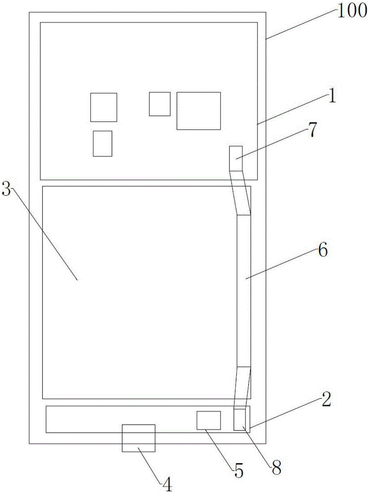
[0064] The first embodiment of the present invention proposes a mobile terminal charging structure, such as image 3 As shown, it includes: a main board 1, a small board 2, and a battery 3, and the battery 3 is arranged between the main board 1 and the small board 2; the main board 1 is provided with electronic components such as a PMIC, a baseband chip, and a PA (power amplifier). device.

[0065] The small board 2 is used to connect the battery charging socket 4, the battery charging socket 4 is a USB interface, the small board 2 is also provided with a direct charge MOS tube 5, and the battery 3 includes two battery connectors, so Said battery connector is arranged on the two ends of the battery 3 through the battery protection plate 6, such as image 3 As shown, the upper battery connector 7 is arranged above the battery, and the lower battery connector 8 is arranged below the battery; the upper battery connector 7 arranged at the upper end buckles the motherboard 1, and ...

Embodiment 2

[0070] The first embodiment of the present invention proposes a mobile terminal charging structure, such as image 3 As shown, it includes: a main board 1, a small board 2, and a battery 3, and the battery 3 is arranged between the main board 1 and the small board 2; the main board 1 is provided with electronic components such as a PMIC, a baseband chip, and a PA (power amplifier). device.

[0071] The small board 1 is used to connect to the battery charging socket 4, the battery charging socket is a USB interface, the small board 2 is also provided with a direct charge MOS tube, the battery 3 includes two battery connectors, and the battery The connectors are arranged at both ends of the battery through the battery protection board 6, such as image 3 As shown, the upper battery connector 7 is arranged above the battery, and the lower battery connector 8 is arranged below the battery; the upper battery connector 7 arranged at the upper end buckles the motherboard 1, and the ...

Embodiment 3

[0077] The third embodiment of the present invention provides a mobile terminal 100, such as image 3 As shown, it includes: a main board 1, a small board 2, and a battery 3, and the battery 3 is arranged between the main board 1 and the small board 2; the main board 1 is provided with electronic components such as a PMIC, a baseband chip, and a PA (power amplifier). device.

[0078] The small board 1 is used to connect to the battery charging socket 4, the battery charging socket 4 is a USB interface, the small board 2 is also provided with a direct charge MOS tube, the battery 3 includes two battery connectors, the The battery connector is arranged on the two ends of the battery through the battery protection board 6, such as image 3 As shown, the upper battery connector 7 is arranged above the battery, and the lower battery connector 8 is arranged below the battery; the upper battery connector 7 arranged at the upper end buckles the motherboard 1, and the lower battery co...


PUM


Abstract

The invention discloses a charging structure of a mobile terminal and the mobile terminal. The charging structure comprises a main board, a small board and a battery, wherein the battery is arranged between the main board and the small board; the small board is used for connecting a battery charging socket, the battery comprises two battery connectors, one battery connector is buckled with the main board, and the other battery connector is buckled with the small board; and a direct charged MOS (Metal Oxide Semiconductor) transistor is arranged on the small board, the battery charging socket is connected with one end of the MOS transistor via the small board, and the other end of the MOS transistor is connected with the battery connector via the small board. By adopting the charging structure, the charging efficiency of the terminal is higher, and the problem of high local heat is solved.

Description

technical field [0001] The invention relates to the technical field of mobile terminals, in particular to a mobile terminal charging structure and a mobile terminal. Background technique [0002] Fast charging is becoming a trend in mobile phone design. The low-voltage and high-current direct charging solution is gradually becoming a mainstream method of fast charging due to the advantages of high current and low heat generation. TI, Fairchild, Qualcomm, MTK, NXP, O2, etc. are launching low-voltage direct charging methods. [0003] The low-voltage high-current direct charging scheme is to charge the battery directly through the MOS tube after the charger is stepped down, and the current in the charging path is consistent with the current charged into the battery. The impedance loss on the path has a great influence on charging efficiency and heat generation. [0004] In the mobile phone design of the half-board solution, in the traditional single-interface battery solution...

Claims


Application Information

Patent Timeline
Patent Type & Authority Applications(China)
IPC IPC(8): H04M1/02H02J7/00
CPCH02J7/00H04M1/0262Y02B40/00
Inventor 夏传龙
Owner NUBIA TECHNOLOGY CO LTD
Why Eureka
Try Eureka