Wind tunnel test platform inclined angle mechanism

A technology of wind tunnel test and platform, which is applied in the field of rotor wind tunnel test, can solve the problems such as the lack of understanding of the aerodynamic characteristics of the new rotor, and achieve the effect of simple structure, low production cost and easy realization

Active Publication Date: 2016-11-30
LOW SPEED AERODYNAMIC INST OF CHINESE AERODYNAMIC RES & DEV CENT
View PDF8 Cites 12 Cited by
  • Summary
  • Abstract
  • Description
  • Claims
  • Application Information

AI Technical Summary

Problems solved by technology

[0003] Compared with foreign countries, domestic research on high-speed helicopters with coaxial rigid rotors is still in its infancy, and the aerodynamic characteristics of the new rotors of this confi...

Method used


Image

  • Wind tunnel test platform inclined angle mechanism
  • Wind tunnel test platform inclined angle mechanism
  • Wind tunnel test platform inclined angle mechanism

Examples


Embodiment approach 1

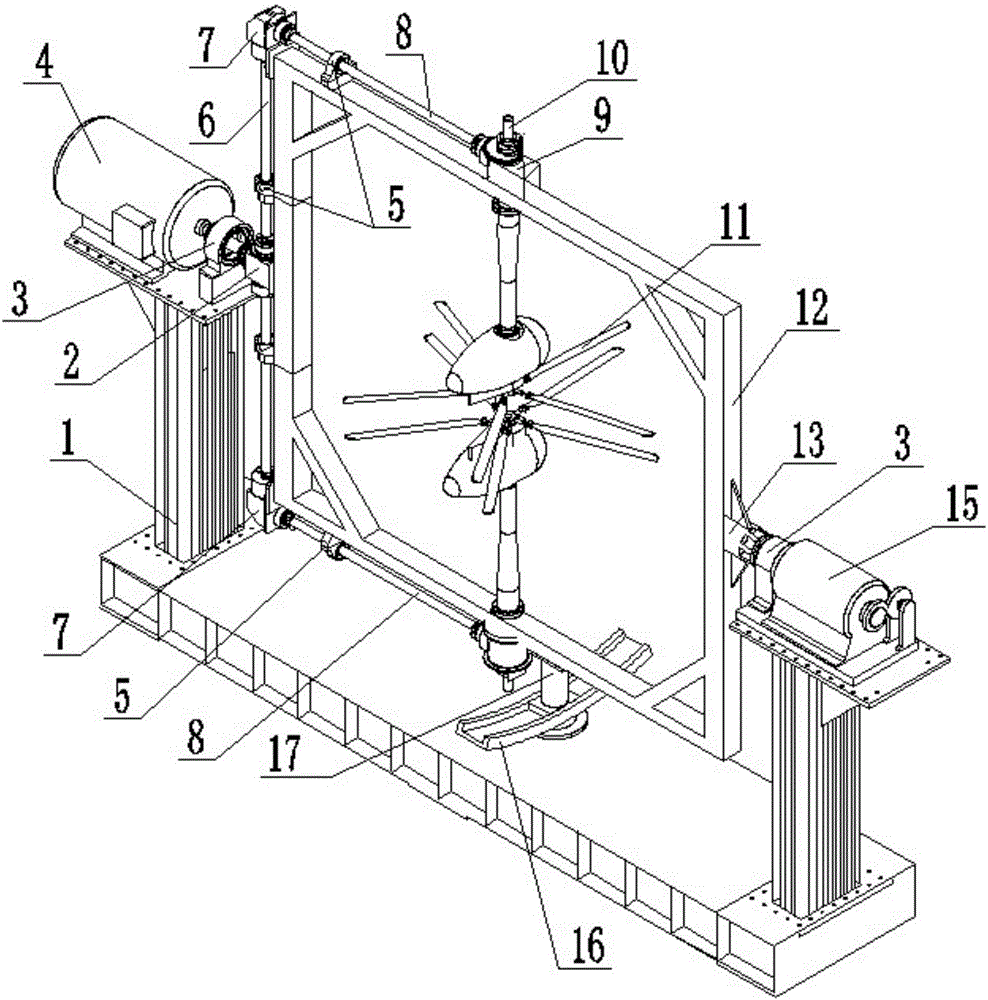
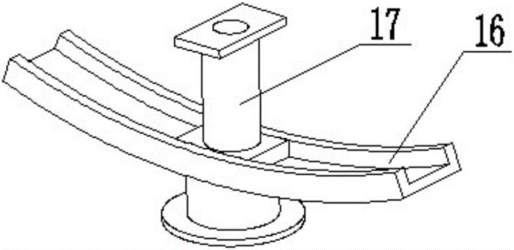
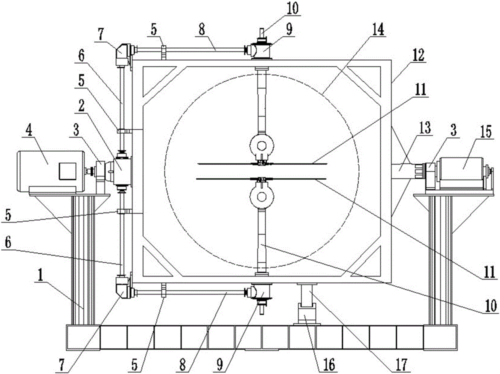
[0030] like figure 1 , image 3 The shown wind tunnel test platform inclination mechanism includes a rotor mounting frame 12, a torque motor 15, a slide rail 16 and a slider 17, and the rotor mounting frame 12 is formed opposite to the rotating shaft support 3 through the left rotating shaft 24 and the right rotating shaft 13 respectively. Rotationally connected and movably connected on the platform 1 , the slide rail 16 is fixedly connected with the platform 1 , and the slider 17 is fixedly connected with the rotor mounting frame 12 . The main motor 4 is fixedly installed on the left column of the platform 1, and the main motor 4 drives the rotor 11 in the rotor installation frame 12 to reverse synchronously, and the torque motor 15 is fixedly installed on the right column of the platform 1. The motor 15 drives the rotor mounting frame 12 to swing relative to the stand 1 through the right rotating shaft 13, the output shaft axis of the main motor 4 coincides with the output ...

Embodiment approach 2

[0035] Compared with Embodiment 1, what described slide rail 16, slide block 17 adopted is electromagnet, and, when torque motor 15 controls rotor mounting frame 12 to stop moving relative to platform 1, described slide block 17 and The sliding rails 16 form mutual adsorption through magnetic force. When the torque motor 15 controls the rotor mounting frame 12 to start moving relative to the stand 1, the electromagnetic attraction between the slider 17 and the slide rail 16 is released, so that the relative movement between the slider 17 and the slide rail 16 is smoother . Others are the same as Embodiment 1.

[0036] After the slide rail 16 and the slide block 17 adopt electromagnets, by powering them off, the magnetic attraction between the slide rail 16 and the slide block 17 can be released, so as to reduce the energy consumption of the torque motor 15. 1, it is more conducive to improving the level of energy saving and consumption reduction.

Embodiment approach 3

[0038] Compared with Embodiment 1 and Embodiment 2, rollers are installed at the bottom of the slider 17, and when the slider 17 moves relative to the slider 16 within the limited range of the slider 16, the slider 17 passes through the rollers and the slider 16. There is rolling friction between them. Others are the same as Embodiments 1 and 2.

[0039] Compared with Embodiments 1 and 2, since the sliding block 17 forms rolling friction between the rollers and the slide rail 16, compared with the sliding friction, the friction loss is lower, so that not only the sliding block 17 and the sliding rail 16 The relative movement between them is smoother, and it is more conducive to improving the level of energy saving and consumption reduction.


PUM


Abstract

The present invention provides a wind tunnel test platform inclined angle mechanism. The mechanism comprises a rotor wing installation frame (12), a torque motor (15), a slide rail (16) and a slide block (17). The rotor wing installation frame (12) is movably connected on a stand (1), the slide rail (16) is fixedly connected with the stand (1), and the slide block (17) is fixedly connected with the rotor wing installation frame (12); and when the torque motor (15) controls the rotor wing installation frame (12) to rotate or stop relative to the stand (1), the slide block (17) performs synchronous movement or stop with the rotor wing installation frame (12) relative to the slide rail (16) in the limited range of the slid rail (16). The wind tunnel test platform inclined angle mechanism can easily realize the inclined angle changing of a rotor wing so as to conveniently perform research of the aerodynamic characteristics of a rigid rotor in the condition of different rotor wing principal axis inclined angles, and can assist in development of the aerodynamic characteristic research of the coaxial rigid rotor and the aerodynamic performance contrastive study of different fixed principal axis inclined angles in the maneuvering flight condition of a helicopter; and moreover, the wind tunnel test platform inclined angle mechanism is simple in structure and low in making cost, etc.

Description

technical field [0001] The invention relates to the technical field of rotor wind tunnel tests, in particular to a wind tunnel test platform inclination mechanism for studying the aerodynamic characteristics of coaxial rigid rotors under different rotor main shaft inclination angles. Background technique [0002] Due to the lack of aerodynamic force, the current conventional configuration helicopter makes it difficult to improve its speed. However, the high-speed helicopter designed with various advanced technologies such as the forward blade concept and the tail propulsion device has broken through the forward flight speed limit of conventional configuration helicopters, and its maximum cruising speed has reached 1.5 times that of conventional configuration helicopters. [0003] Compared with foreign countries, domestic research on coaxial rigid rotor high-speed helicopters is still in its infancy, and the understanding of the new rotor aerodynamic characteristics of the he...

Claims


Application Information

Patent Timeline
IPC IPC(8): G01M9/04
CPCG01M9/04
Inventor 黄明其彭先敏杨永东梁鉴章贵川
Owner LOW SPEED AERODYNAMIC INST OF CHINESE AERODYNAMIC RES & DEV CENT
Why Eureka
Try Eureka