Image identification method of stirring friction welding arc stripe interval

A friction stir welding and arc-shaped technology, which is applied in character and pattern recognition, measuring devices, instruments, etc., can solve the problem of not being able to obtain the arc-shaped pattern spacing in real time, so as to improve the degree of recognition, increase the value of research, and enrich the acquisition methods Effect

Inactive Publication Date: 2012-11-14
NANJING UNIV OF AERONAUTICS & ASTRONAUTICS
View PDF0 Cites 35 Cited by
  • Summary
  • Abstract
  • Description
  • Claims
  • Application Information

AI Technical Summary

Problems solved by technology

[0005] The purpose of the present invention is to solve the problem that the arc-shaped groove spacing cannot be obtained in real time in the existing friction stir welding process, thereby affecting the research on the formation mechanism of friction stir welding, and to invent a friction stir welding arc-shaped groove spacing that can monitor the arc-shaped groove spacing in real time image recognition method

Method used


Image

  • Image identification method of stirring friction welding arc stripe interval
  • Image identification method of stirring friction welding arc stripe interval
  • Image identification method of stirring friction welding arc stripe interval

Examples


Embodiment Construction

[0051] The present invention will be further described below in conjunction with the accompanying drawings and embodiments.

[0052] like Figure 1-19 shown.

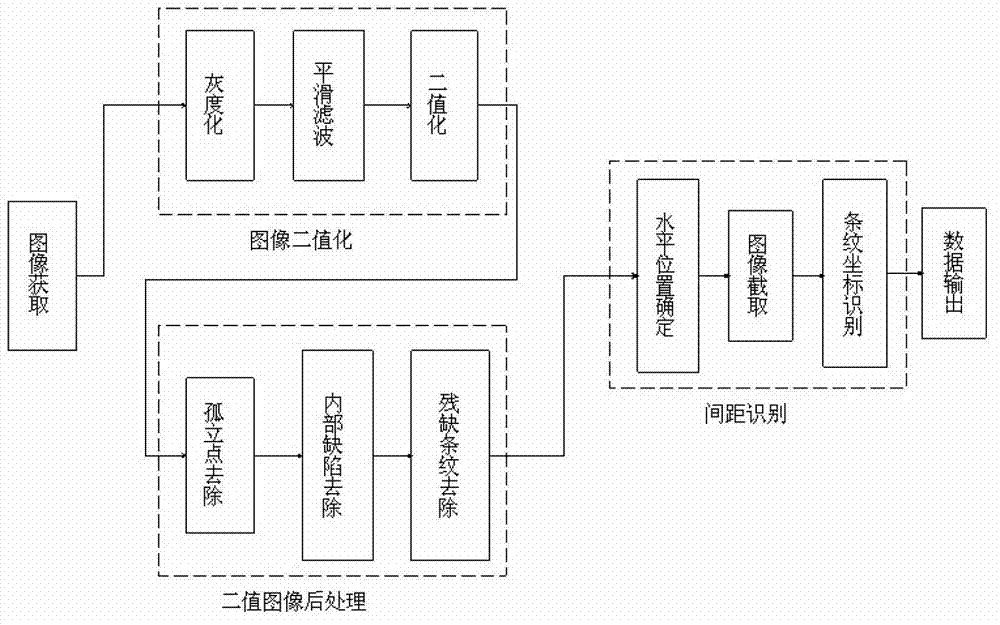
[0053] An image recognition method for friction stir welding arc groove spacing, the process is as follows figure 1 As shown, it includes the following steps:

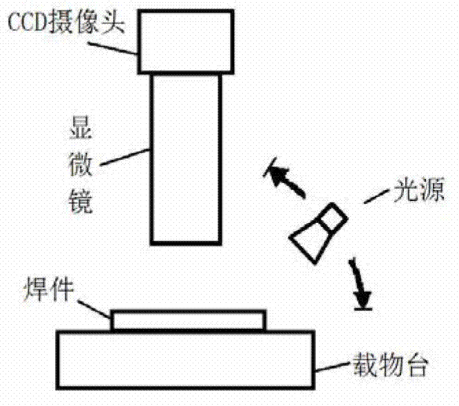
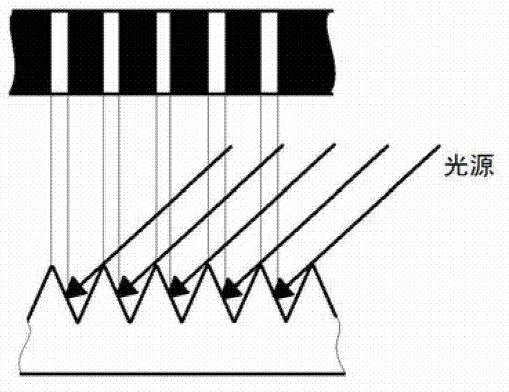
[0054] (1) Acquisition of arc pattern images, including the following steps:

[0055] When image acquisition is performed on the arc pattern on the friction stir welding surface, the light source with a certain angle of incidence relative to the arc pattern surface is the only light source, and the image acquisition device such as figure 2 As shown, the incident light source effect diagram is as follows image 3 As shown, the angle between the incident angle and the horizontal plane should be less than 90 degrees, image 3 The incident angle is between 45 degrees and 60 degrees.

[0056] (2) Binarization of the arc pattern image, including the following s...


PUM


Abstract

The invention discloses an image identification method of stirring friction welding arc stripe interval. The image identification method is characterized by mainly comprising the steps of: obtaining image, carrying out binarization processing on the image, carrying out post processing on the binary image and detecting and calculating the arc stripe interval, firstly, obtaining a microscopic picture of a stirring friction welding arc stripe tool; and then, performing gray scale, wave filtering and binarization processing on the microscopic picture of the arc stripe tool; removing the isolated points, the interior stripe detects and the incomplete edge stripes of the binary image; and finally, determining the arc stripe interval calculation range, calculating the arc stripe interval and processing the data. The image identification method of stirring friction welding arc stripe distance disclosed by the invention greatly enriches the obtaining method of arc stripe parameters and provides certain foundation for research of the arc stripe parameters in the stirring friction welding.

Description

technical field [0001] The invention relates to a mechanical processing technology, in particular to a friction stir welding technology, in particular to an image recognition method for the distance between friction stir welding arc lines. Background technique [0002] Friction stir welding (FSW) originated in the UK in the early 1990s. The main working principle is that the cylindrical stirring head is inserted into the joint of the workpiece, and the friction heat generated by high-speed rotation makes the material at the joint warm and soften, and at the same time, it is stirred by the cylinder. The stirring effect of the head rotation makes the materials on both sides stick to each other, and the stirring head moves along the welding seam to finally achieve the welding effect. [0003] Compared with other classic welding methods, friction stir welding has more distinctive features. The welding process does not require other welding materials but the weldments are directl...

Claims


Application Information

Patent Timeline
Patent Type & Authority Applications(China)
IPC IPC(8): G06K9/60G01B11/14
Inventor 黎向锋左敦稳辛铖浩江世好孙玉利汪洪峰宋波张圣斌邓永芳
Owner NANJING UNIV OF AERONAUTICS & ASTRONAUTICS
Why Eureka
Try Eureka