Six-degree-of-freedom fire extinguishing manipulator for power distribution station fire-fighting robot

A fire-fighting robot and degree-of-freedom technology, applied in manipulators, program-controlled manipulators, fire rescue and other directions, can solve the problems of reduced firefighting efficiency of manual on-site firefighting operations, reduced working time of firefighting operations, threats to the personal safety of firefighters, and low overall efficiency of firefighting and firefighting, etc. Wide range of fire-extinguishing spray, high rigidity, and the effect of large fire-extinguishing spray range

Active Publication Date: 2016-12-07
骆碧卿
View PDF5 Cites 1 Cited by
  • Summary
  • Abstract
  • Description
  • Claims
  • Application Information

AI Technical Summary

Problems solved by technology

[0004] For fire fighting and fire extinguishing methods, manual fire extinguishers are often carried into the fire fighting site for manual fire fighting operations. Such existing fire fighting methods are dangerous and pose a great threat to the personal safety of firefighters. There are a lot of people who died in firefighting operations; at the same time, the efficiency of manual on-site firefighting operations will gradually decrease with the prolongation of the operation time, and the overall efficiency, speed and flexibility of firefighting operations are low.

Method used


Image

  • Six-degree-of-freedom fire extinguishing manipulator for power distribution station fire-fighting robot
  • Six-degree-of-freedom fire extinguishing manipulator for power distribution station fire-fighting robot
  • Six-degree-of-freedom fire extinguishing manipulator for power distribution station fire-fighting robot

Examples


Embodiment Construction

[0022] In order to make the technical means, creative features, goals and effects achieved by the present invention easy to understand, the present invention will be further described below in conjunction with specific illustrations.

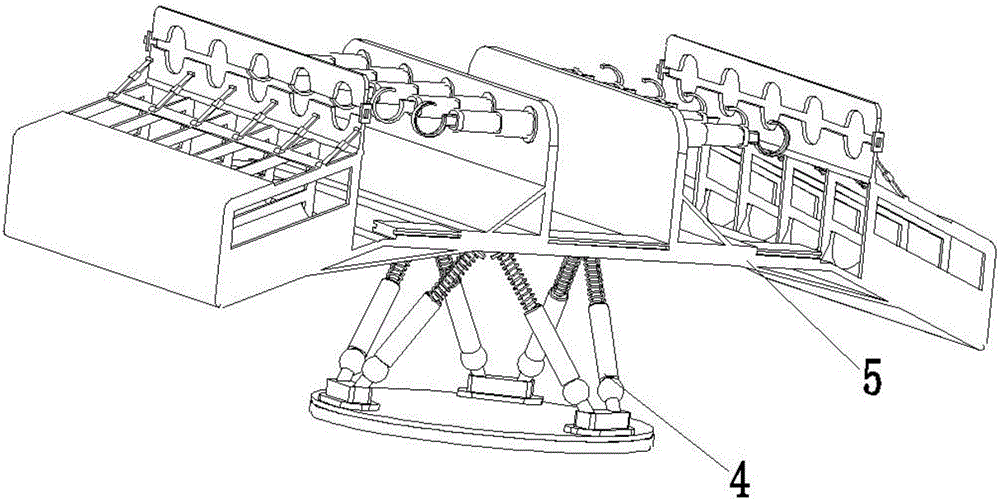
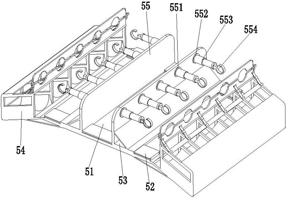
[0023] Such as Figure 1 to Figure 4 As shown, a six-degree-of-freedom fire-extinguishing manipulator for a distribution station fire-fighting robot includes a Stewart parallel mechanism 4 and a fire extinguishing device 5; 5 phase connections.

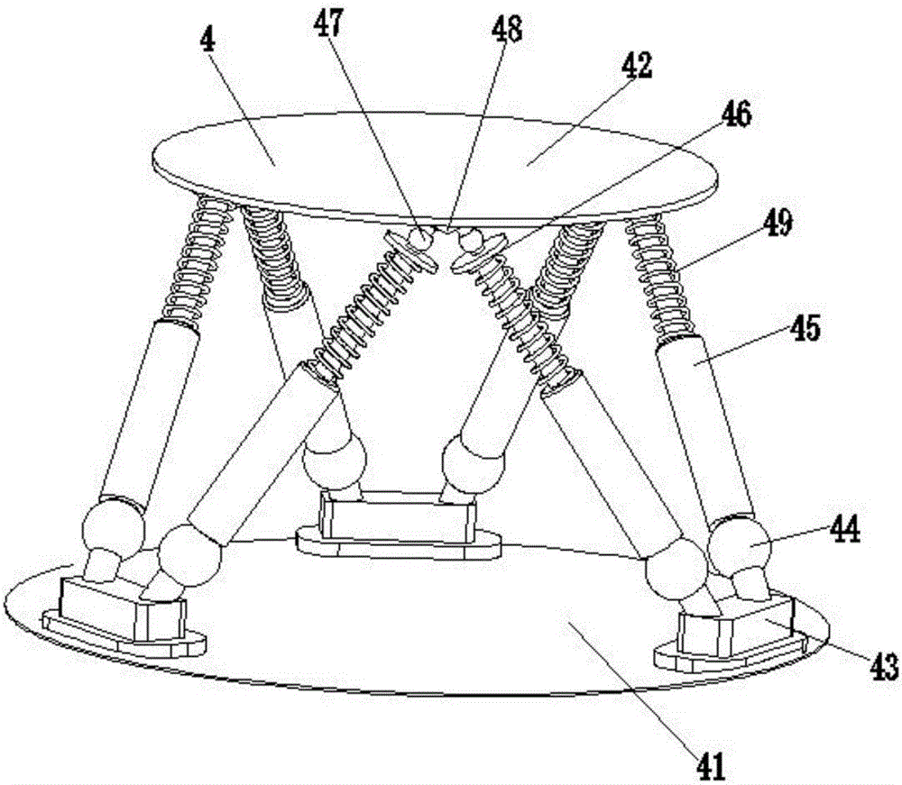
[0024] Such as figure 2As shown, the Stewart parallel mechanism 4 includes a fixed platform 41, a moving platform 42, a connecting seat 43, an upper ball hinge 44, an electric push rod 45, a disc seat 46, a lower ball hinge 47, a triangular seat 48 and a limit spring 49; the number of the connecting seat 43 and the triangular seat 48 is three, the number of the upper ball hinge 44, the electric push rod 45, the plate seat 46 and the lower ball hinge 47 are all six, the fixed platform 41 and the movin...


PUM


Abstract

The invention relates to a six-degree-of-freedom fire extinguishing manipulator for a power distribution station fire-fighting robot. The six-degree-of-freedom fire extinguishing manipulator comprises a Stewart parallel mechanism and a fire extinguishing device. The Stewart parallel mechanism is located under the fire extinguishing device. The upper end of the Stewart parallel mechanism is connected with the fire extinguishing device. The six-degree-of-freedom fire extinguishing manipulator can carry out fire protection and fire extinguishing operation when a fire breaks out in a power distribution station. The six-degree-of-freedom fire extinguishing manipulator is high in automation degree, large in fire extinguishment jet range and high in fire extinguishing efficiency and safety. The problem of large risks during manual fire protection and fire extinguishing in the power distribution station is solved. The six-degree-of-freedom fire extinguishing manipulator is provided with the 6-SPS Stewart parallel mechanism and can conduct three-translation and three-rotation six-degree-of-freedom movement in space. On one hand, the orientation angle of the fire extinguishing device is adjusted, and on the other hand, the effect of absorbing shock of the fire extinguishing device is achieved, so that the fire extinguishing device is in a horizontal steady state all the time when the six-degree-of-freedom fire extinguishing manipulator moves bumpily, and stored fire extinguishers are protected against potential safety hazards caused by too heavy jittering.

Description

technical field [0001] The invention relates to the field of electric fire-fighting equipment, in particular to a six-degree-of-freedom fire-extinguishing manipulator for a distribution station fire-fighting robot. Background technique [0002] Electricity is an energy powered by electric energy. It was invented in the 1870s. The invention and application of electric power set off the second industrialization climax and became one of the three scientific and technological revolutions in the world since the 18th century in human history. Since then, technology has changed people. The large-scale power system that appeared in the 20th century is one of the most important achievements in the history of human engineering science. It is a power production and consumption system composed of power generation, power transmission, power transformation, power distribution and power consumption. The primary energy is converted into electricity through mechanical energy devices, and the...

Claims


Application Information

Patent Timeline
IPC IPC(8): A62C37/00A62C31/28B25J9/00
CPCA62C31/28A62C37/04B25J9/0057
Inventor 虞田乐
Owner 骆碧卿
Why Eureka
Try Eureka