Oil well cleaning equipment

A technology for cleaning equipment and oil wells, which is applied in the directions of cleaning hollow objects, cleaning methods and utensils, chemical instruments and methods, etc., can solve the problems of backward flushing methods, low efficiency, poor cleaning effect, etc., and achieve automatic and efficient cleaning and high cleaning efficiency. Effect

Active Publication Date: 2018-06-05
YANCHENG HIROMICHI PETROLEUM MACHINERY CO LTD
View PDF6 Cites 0 Cited by
  • Summary
  • Abstract
  • Description
  • Claims
  • Application Information

AI Technical Summary

Problems solved by technology

[0003] At present, the tubing of oil wells is cleaned in an open manner, and is directly flushed beside the well. The flushing method is backward, and the cleaning effect is poor and the efficiency is low.

Method used


Image

  • Oil well cleaning equipment
  • Oil well cleaning equipment
  • Oil well cleaning equipment

Examples


Embodiment Construction

[0015] In order to make the technical means, creative features, goals and effects achieved by the present invention easy to understand, the present invention will be further elaborated below in conjunction with the embodiments.

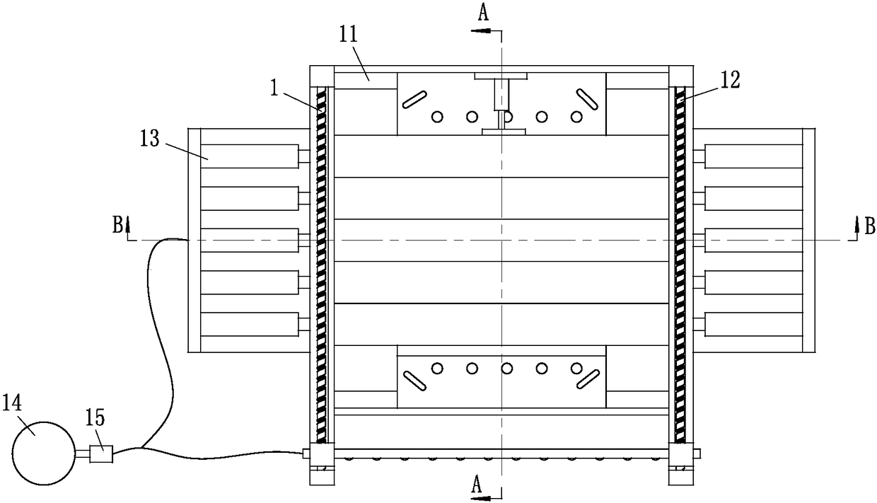
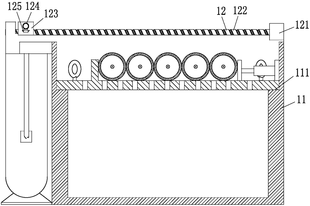
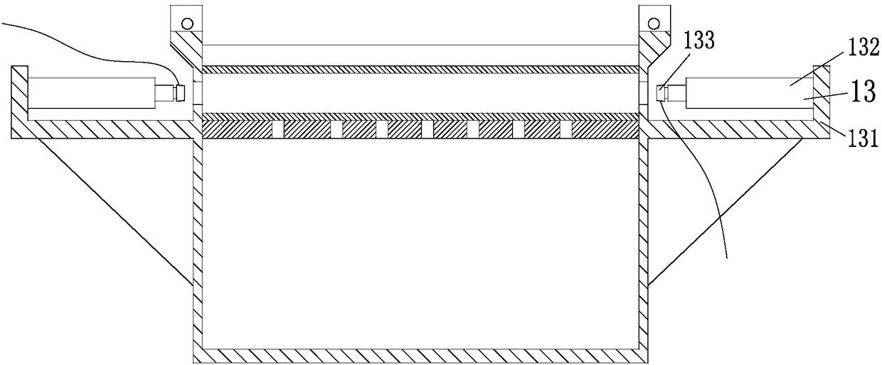
[0016] Such as figure 1 , figure 2 and image 3 As shown, a cleaning device for an oil well according to the present invention includes a cleaning device 1, and the cleaning device 1 includes a cleaning chamber 11, an external cleaning device 12, an internal cleaning device 13, a heating furnace 14 and a cleaning pump 15. The cleaning chamber 11 as a whole is a cubic structure with an open upper end, the upper part of the cleaning chamber 11 is provided with a stepped groove 111, and the left and right sides of the upper part of the cleaning chamber 11 are evenly provided with through holes; the external cleaning device 12 Including an outer washing motor 121, an outer washing screw 122, a slider 123, a water spraying hard pipe 124 and an outer was...


PUM


Abstract

The invention relates to the field of oil equipment, in particular to cleaning equipment used for an oil well. The cleaning equipment comprises a cleaning device. The cleaning device comprises a cleaning bin, an external cleaning unit, an internal cleaning unit, a heating furnace and a cleaning pump. The external cleaning unit comprises external cleaning motors, external cleaning screws, sliding blocks, water spray rigid tubes and external cleaning spray nozzles. The internal cleaning unit comprises internal cleaning support plates, internal cleaning air cylinders and internal cleaning spray nozzles. The heating furnace is a fire tube type superconduction boiler. According to the cleaning equipment used for the oil well, automatic and efficient cleaning for the inner wall and the outer wall of an oil tube can be achieved and the cleaning efficiency is high.

Description

technical field [0001] The invention relates to the field of petroleum equipment, in particular to cleaning equipment for oil wells. Background technique [0002] With the rapid development of my country's economy, the contradiction between energy shortage, environmental pollution and economic development has become increasingly prominent, so the country advocates environmental protection, energy-saving projects with independent intellectual property rights. Entering the 21st century, the relevant state departments have proposed a series of new concepts of environmental protection measures such as environmental protection, energy conservation and emission reduction, and at the same time shut down a group of small and medium-sized enterprises that are not suitable for continued development, such as small scale, high energy consumption, and large environmental pollution, and vigorously improve the national economy. living environment. The petroleum industry is the country's b...

Claims


Application Information

Patent Timeline
Patent Type & Authority Patents(China)
IPC IPC(8): B08B9/023B08B9/049B08B13/00
CPCB08B9/023B08B9/049B08B13/00
Inventor 李哲辉
Owner YANCHENG HIROMICHI PETROLEUM MACHINERY CO LTD
Why Eureka
Try Eureka