Force/position controllable flexible driver

A flexible driver and controllable technology, applied in the field of robotics, can solve the problems of the inability to guarantee the output force of the driver, and it is difficult to meet the requirements, and achieve the effect of alleviating the internal force and protecting the system itself.

Active Publication Date: 2016-12-07
YANSHAN UNIV
View PDF7 Cites 7 Cited by
  • Summary
  • Abstract
  • Description
  • Claims
  • Application Information

AI Technical Summary

Problems solved by technology

Its shortcoming is: since the stiffness value of the driver is changing, the output force of the driver cannot be guaranteed, and it is difficult to meet the requirements of some specific industrial applications.

Method used


Image

  • Force/position controllable flexible driver
  • Force/position controllable flexible driver
  • Force/position controllable flexible driver

Examples


Embodiment Construction

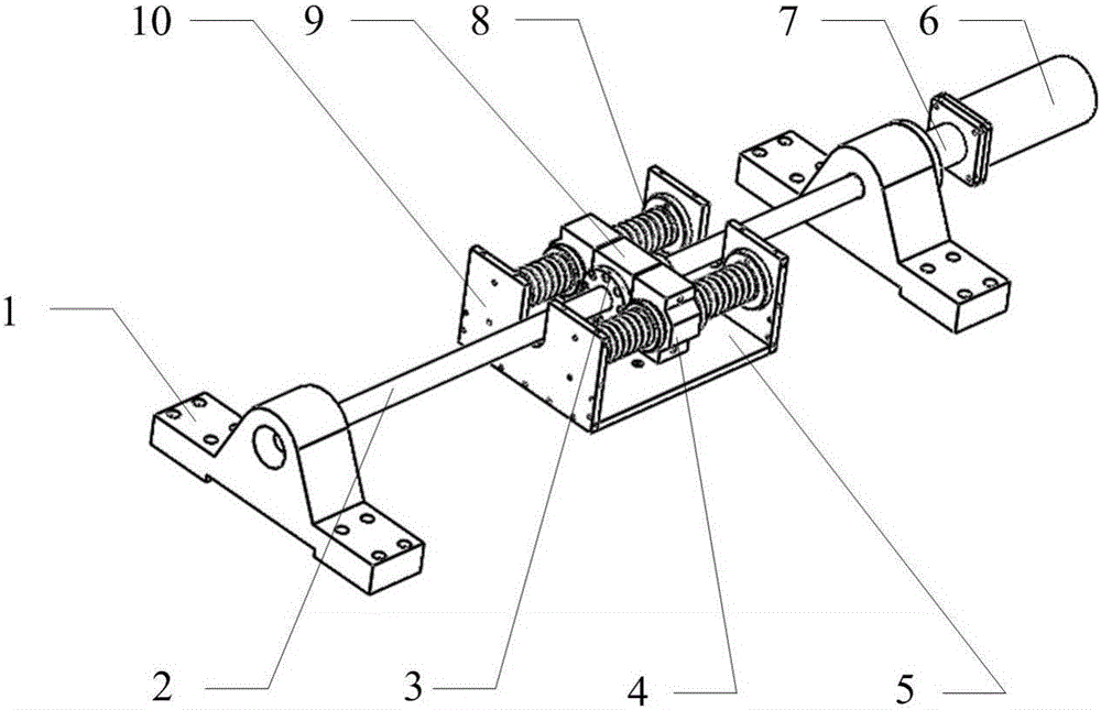
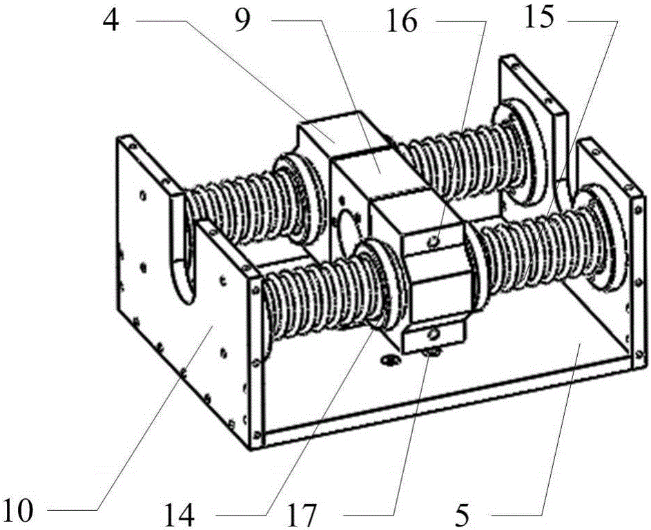
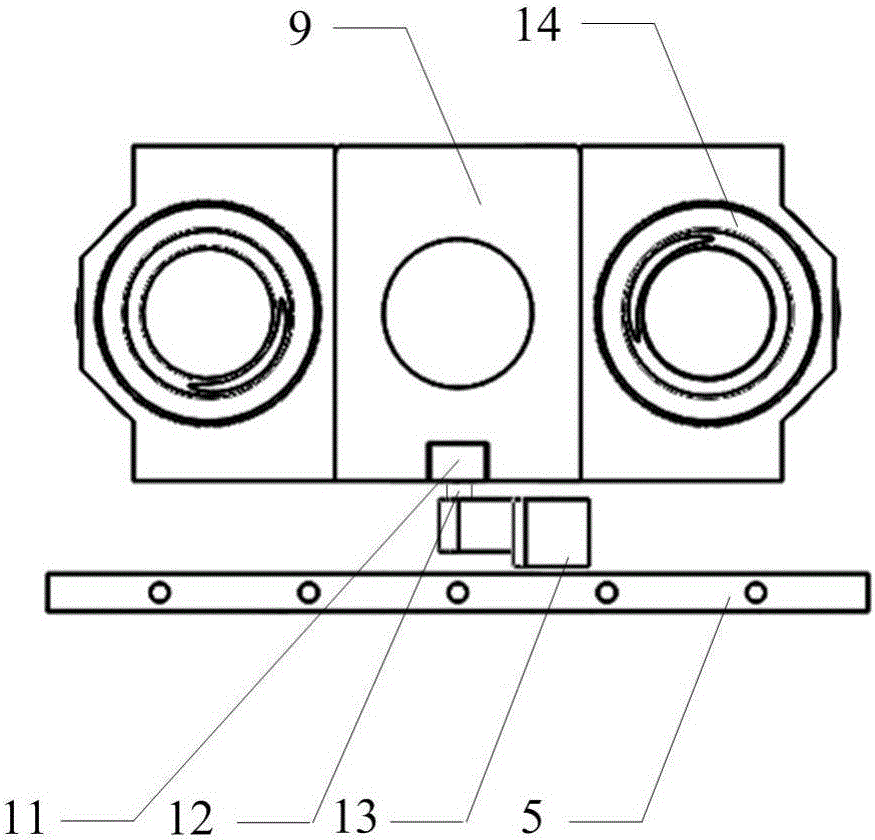
[0020] exist figure 1 , figure 2 , image 3 and Figure 4 In the schematic diagram of the present invention shown, the driving device includes a bracket, a lead screw, a servo motor, a shaft coupling, a nut connector, a long bolt A, a sliding bearing, and an optical shaft. Two identical brackets 1 are respectively provided with through holes, and the two ends of the screw 2 pass through the through holes of the two brackets respectively, and one end of the screw extends to the outside of the brackets, and is connected with the output shaft of the servo motor 6 through the coupling. Shaft 7 is connected. Insert the nut connector 9 on the lead screw, one side of the nut connector is provided with a nut 3, the nut is threadedly connected with the lead screw, and the two ends of the nut connector are respectively connected with a sliding bearing 4 through a long bolt A16. An optical shaft 15 is respectively plugged into each sliding bearing, and both ends of the optical shaft...


PUM


Abstract

Provided is a force / position controllable flexible driver. Polished shafts on the two sides of a sliding bearing of a drive device are each sleeved with springs of a flexible detection device. The other end of a grating ruler of the flexible detection device is connected with a power output plate of a drive output device. A lead screw of the drive device is arranged in a groove in a baffle of the drive output device. The other end of the spring is embedded in the groove in the inner wall of the baffle of the corresponding drive output device. On the basis that a redundant drive parallel-connection mechanism has no internal force motion, both position control and force control over the redundant drive parallel-connection mechanism can be achieved, and accordingly the force / position controllable flexible driver is widely applied to different working places.

Description

technical field [0001] The invention belongs to the field of robots, in particular to a flexible driver. Background technique [0002] Compared with general parallel mechanisms, redundant drive parallel mechanisms often have the advantages of high stiffness, no singularity in the working space and better dynamic characteristics. However, there are also some problems in actual production and application for redundantly driven parallel mechanisms. Since the number of degrees of freedom of the redundantly driven parallel mechanism is greater than the number of its drives, in actual applications such as redundantly driven parallel machine tools and robots, there are often internal forces generated by factors such as gaps or control inconsistencies, which lead to mechanical systems. death or even destruction. [0003] At present, parallel machine tools and robots that are more researched are usually based on rigid drivers with high torque and high stiffness. The way to realize ...

Claims


Application Information

Patent Timeline
Patent Type & Authority Applications(China)
IPC IPC(8): B25J9/12B25J9/00
CPCB25J9/003B25J9/12
Inventor 赵永生周鑫丰宗强许允斗姚建涛
Owner YANSHAN UNIV
Why Eureka
Try Eureka