
Stepping cutting device

A cutting device, step-by-step technology, applied in the direction of fine working devices, manufacturing tools, stone processing equipment, etc., can solve the problems of prolonged cutting time, high tension, affecting cutting efficiency, etc., to improve cutting efficiency and convenience. Removal and installation, easy cutting effect

Inactive Publication Date: 2018-02-13
重庆洪毅模塑有限公司
View PDF5 Cites 0 Cited by
  • Summary
  • Abstract
  • Description
  • Claims
  • Application Information

AI Technical Summary

Problems solved by technology

[0004] The problems of the above devices are: 1. When installing the diamond wire, because the distance between the two rollers cannot be adjusted, it is impossible to ensure that the installed diamond wire is at a high tension; When cutting polysilicon, the diamond wire cutting strength cannot be guaranteed, which will lengthen the cutting time and affect the cutting efficiency

Method used


Image

  • Stepping cutting device

Examples


Embodiment Construction

[0013] The present invention will be described in further detail below by means of specific embodiments:

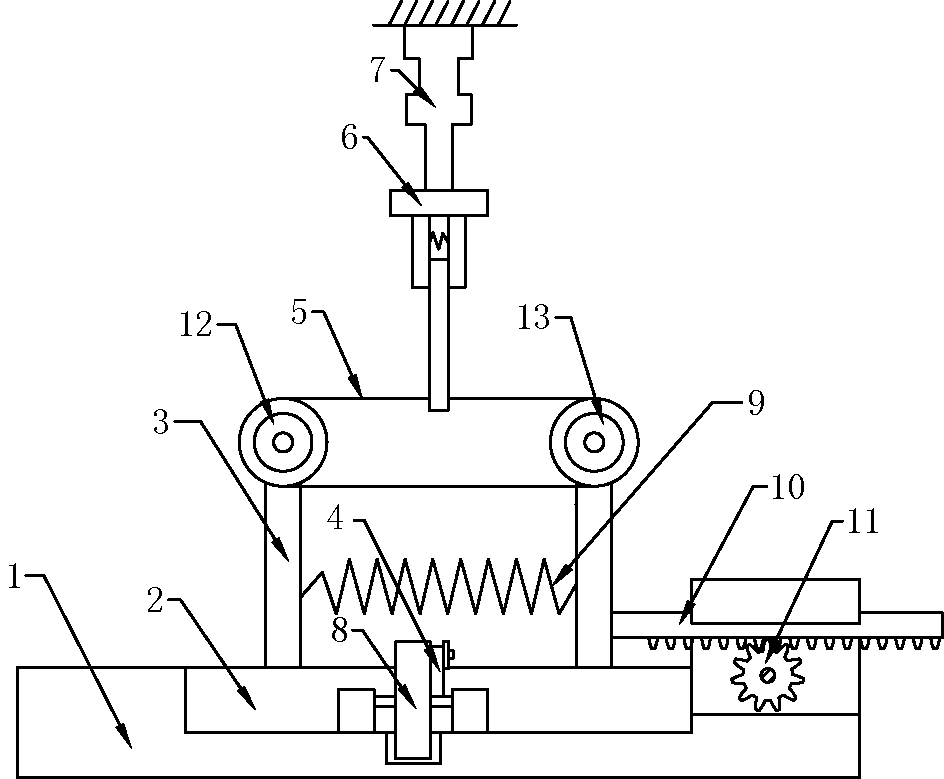
[0014] The reference signs in the drawings of the description include: frame 1, base 2, fixed rod 3, connecting rod 4, diamond wire 5, claw 6, cylinder 7, turntable 8, spring 9, rack 10, gear 11, drive Roller 12, driven roller 13.

[0015] Example basic reference figure 1 Shown: a step-by-step cutting device, including a frame 1 and a diamond wire 5, the frame 1 is provided with a relative driving roller 12 and a driven roller 13, and the diamond wire 5 is wound between the driving roller 12 and the driven roller 13 , the driving roller 12 is connected with a third stepping motor, the frame 1 is connected with a base 2 that slides back and forth, the left side of the base 2 is connected with a fixed rod 3, and the driving roller 12 is connected to the top of the fixed rod 3 in rotation, and the base 2 is connected to the right side of the fixed rod 3. The side is connec...


PUM


Abstract

The invention discloses a step type cutting device. The step type cutting device comprises a machine frame and a diamond wire. The machine frame is provided with a driving roller and a driven roller which are opposite, the diamond wire is wound around the driving roller and the driven roller, and a base is connected to the machine frame in a sliding manner; a fixing rod is fixedly connected to the base, the driving roller is rotationally connected to the top of the fixing rod, and a supporting rod is connected to the base in a sliding manner; the driven roller is arranged at the top of the supporting rod, a rack is connected to the supporting rod and meshed with a gear, the gear is rotationally connected to the machine frame; a rotation disc is rotationally connected to the machine frame, a connecting rod is hinged to the rotation disc, and one side, along the sliding direction of the base is hinged to the connecting rod; a gripping jaw is arranged above the diamond wire, and a pushing rod is connected to the gripping jaw and connected to the machine frame in a sliding manner; through matching of the gear and the rack, the tension degree of the diamond wire can be conveniently adjusted; and through the arrangement of the rotation disc and the connecting rod, the diamond wire can rotate at a high speed while moving in a reciprocated manner, and therefore polycrystalline silicon can be cut by the diamond wire more easily, and the cutting efficiency is improved accordingly.

Description

technical field [0001] The invention relates to a cutting device, in particular to a step-by-step cutting device. Background technique [0002] Many things in the industry are cut with diamond wire, such as polysilicon slices in the photovoltaic field. The material of the diamond wire is important. At present, the mainstream silicon wafer cutting wire used in the photovoltaic field is an ultra-fine cutting steel wire with a diameter of about 100 microns. As the name suggests, diamond wire is related to diamond. It is generally a diamond cutting wire made of tiny diamond particles embedded on the wire; we know that diamond is a superhard and widely used cutting material. Serrated teeth, which increase the cutting ability of the steel wire, can greatly speed up the cutting speed. [0003] When using cutting wire to cut polysilicon, the diamond wire is first fixed on the reciprocating cutting device. The reciprocating cutting device includes a frame, and two rollers are fixe...

Claims


Application Information

Patent Timeline
Patent Type & Authority Patents(China)
IPC IPC(8): B28D5/00
CPCB28D5/00B28D5/0023
Inventor 梅秀春
Owner 重庆洪毅模塑有限公司
Learn More