A structure to prevent the rubber in the gate from breaking in the mold

An in-mold and rubber material technology is applied in the structural field where the rubber material is broken in the mold, which can solve the problems of mold damage, inability to reset, and remaining in the mold, so as to improve the service life, avoid flow marks and air bubbles, and reduce glue The effect of the amount

Active Publication Date: 2018-03-30
WUHAN LIAOYUAN MOLDING
View PDF5 Cites 0 Cited by
  • Summary
  • Abstract
  • Description
  • Claims
  • Application Information

AI Technical Summary

Problems solved by technology

[0002] Due to the particularity of the product structure, in order to meet the appearance requirements of the grille, a hidden glue gate must be used, and the connection between the product and the rubber in the gate is the weakest point, and the glue in the gate is pushed out During the process, the product and the rubber in the gate are easily broken and separated under the action of the mold sticking force, resulting in the product being taken away by the robot, while the rubber in the gate remains in the mold. When the mold is closed, there is no gate glue taken out. The material in the mold will make the parts in the mold unable to reset, which will cause the parts in the mold to squeeze each other, causing serious damage to the mold

Method used


Image

  • A structure to prevent the rubber in the gate from breaking in the mold
  • A structure to prevent the rubber in the gate from breaking in the mold
  • A structure to prevent the rubber in the gate from breaking in the mold

Examples


Embodiment Construction

[0018] The present invention will be further described in detail below through specific embodiments in conjunction with the accompanying drawings.

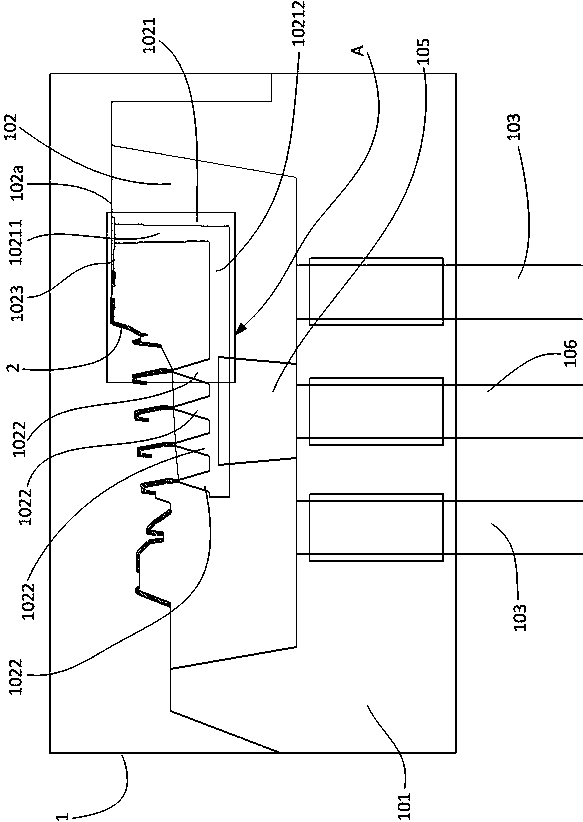
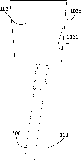
[0019] Please refer to Figure 1 to Figure 5 , the embodiment of the present invention prevents the rubber material in the gate from breaking in the mold structure, which includes a front mold and a rear mold 1 that cooperates with the front mold, and the front mold and the rear mold 1 are molded together to form a mold cavity. The back mold 1 is provided with a glue feeding channel, and the back mold 1 includes a back mold core 101, a straight jack block 102 arranged in the back mold core 101, and a straight jack rod 103 for driving the straight jack block 102 to move up and down. , the upper end of the rear mold 1 has a cavity forming portion 104 that forms the peripheral surface of the cavity, and one side of the straight top block 102 is provided with a glue inlet channel forming portion 1021 that forms the peripheral surface ...


PUM


Abstract

The invention relates to a structure capable of preventing a sizing material in a pouring gate from being broken in a mold. The structure is differently characterized by comprising a front mold and a rear mold, wherein a sizing material feeding channel is formed in the rear mold; the rear mold comprises a rear mold core, a straight ejector block and a straight ejector rod; a cavity forming part used for forming the peripheral surface of a cavity part is arranged at the upper end of the rear mold; a sizing material feeding channel forming part used for forming the peripheral surface of a sizing material feeding channel part is formed in one side of the straight ejector block; the sizing material feeding channel forming part is matched with the rear mold core to form a sizing material feeding channel; the sizing material feeding channel forming part comprises a first section extended downward from the upper end of the straight ejector block and a second section connected with the first section and transversely extended to the lower part of the cavity forming part; pouring gate forming parts connected with the cavity forming part are formed in the second section of the sizing material feeding channel; a connection channel forming part used for connecting the cavity forming part with the first section of the sizing material feeding channel is also formed in the upper end of the straight ejector block; material preventing bulges are formed near the connection channel forming part on the cavity forming part. The structure is capable of taking the product and the sizing material in the pouring gate together.

Description

technical field [0001] The invention relates to the field of injection molds, in particular to a structure for preventing rubber in a gate from breaking in the mold. Background technique [0002] Due to the particularity of the product structure, in order to meet the appearance requirements of the grille, a hidden glue gate must be used, and the connection between the product and the rubber in the gate is the weakest point, and the glue in the gate is pushed out During the process, the product and the rubber in the gate are easily broken and separated under the action of the mold sticking force, resulting in the product being taken away by the robot, while the rubber in the gate remains in the mold. When the mold is closed, there is no gate glue taken out. The material will make the parts in the mold unable to reset, which will cause the parts in the mold to squeeze each other, causing serious damage to the mold. Contents of the invention [0003] The purpose of the prese...

Claims


Application Information

Patent Timeline
Patent Type & Authority Patents(China)
IPC IPC(8): B29C45/26B29C45/27
CPCB29C45/0025B29C45/2602B29C45/2708B29C2045/0041
Inventor 徐凯贤牟必山
Owner WUHAN LIAOYUAN MOLDING
Why Eureka
Try Eureka