

A crane trolley anti-gnawing rail system
A technology of cranes and trolleys, applied in the directions of traveling mechanism, load hanging components, transportation and packaging, etc., can solve problems such as inconvenient correction, injury to human life, inconvenient analysis, etc., to achieve easy maintenance and maintenance, prevention of accidents, simple structure Effect
- Summary
- Abstract
- Description
- Claims
- Application Information
AI Technical Summary
Problems solved by technology
Method used
Image

Examples
Embodiment 1
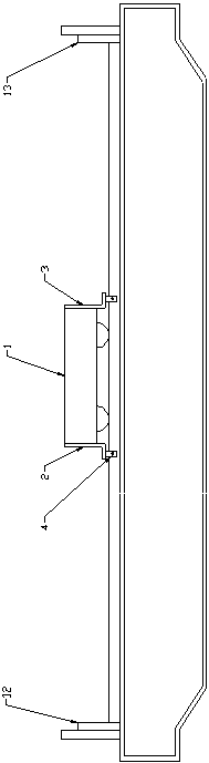
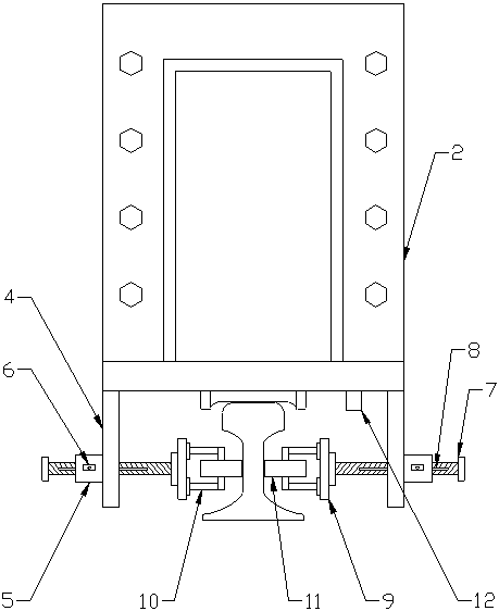
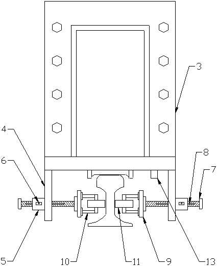
[0015] Such as Figure 1-3 As shown, a crane trolley anti-gnawing rail system, it includes a trolley body 1, the left and right ends of the trolley body 1 are respectively provided with an L-shaped end plate A2 and an end plate B3, the bottom of the end plate A2 A laser emitter A4 is arranged on the right side of the center of the surface, a laser emitter B5 is arranged on the left side of the center of the lower surface of the end plate B3, and mounting plates 4 are arranged at both ends of the lower surface of the end plate A2 and the end plate B3, The center of the outer surface of the mounting plate 4 is provided with an adjustment seat 5, the center of the adjustment seat 5 is provided with a threaded hole penetrating the installation plate, and the side of the adjustment seat 5 is provided with a pin hole passing through the axis. A pin shaft 6 is arranged in the pin hole of the shaft, and an adjusting rod 7 is arranged in the adjusting seat 5. The adjusting rod 7 is pro...
Embodiment 2
[0018] Such as Figure 1-3 As shown, a crane trolley anti-gnawing rail system, it includes a trolley body 1, the left and right ends of the trolley body 1 are respectively provided with an L-shaped end plate A2 and an end plate B3, the bottom of the end plate A2 A laser emitter A4 is arranged on the right side of the center of the surface, a laser emitter B5 is arranged on the left side of the center of the lower surface of the end plate B3, and mounting plates 4 are arranged at both ends of the lower surface of the end plate A2 and the end plate B3, The center of the outer surface of the mounting plate 4 is provided with an adjustment seat 5, the center of the adjustment seat 5 is provided with a threaded hole penetrating the installation plate, and the side of the adjustment seat 5 is provided with a pin hole passing through the axis. A pin shaft 6 is arranged in the pin hole of the shaft, and an adjusting rod 7 is arranged in the adjusting seat 5. The adjusting rod 7 is pro...
PUM
 Abstract
Description
Claims
Application Information