Block brake friction plate warning device

An alarm device and brake technology, applied in the direction of brake type, mechanical equipment, etc., can solve the problems of uncertain location and environment of the equipment, frequent contact of unfavorable personnel, and inability to exert the strength of professional inspections to avoid false alarms and The effect of frequent alarms

Inactive Publication Date: 2016-12-07
SHANDONG IRON & STEEL CO LTD
View PDF6 Cites 2 Cited by
  • Summary
  • Abstract
  • Description
  • Claims
  • Application Information

AI Technical Summary

Problems solved by technology

Therefore, there are several unreasonable factors in the existing point inspection methods for block brake friction plates: 1. It needs to be frequently observed and measured directly by the naked eye of personnel; 2. The environment where the equipment is located is uncertain, which is not conducive to frequent contact with personnel; 3. , It is necessary to set up professionals for spot inspection and maintenance, and it is impossible to give full play to the power of professional spot checks

Method used


Image

  • Block brake friction plate warning device
  • Block brake friction plate warning device
  • Block brake friction plate warning device

Examples


Embodiment 1

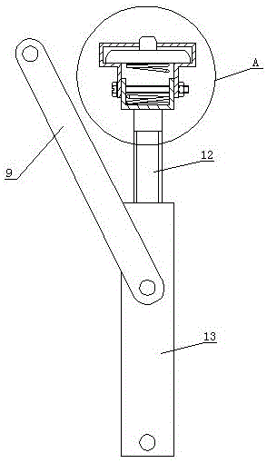
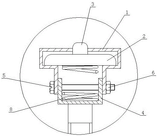
[0035] Such as Figure 1 to Figure 7 As shown, the present invention includes a switch support seat 1, a control switch 2 is arranged in the switch support seat 1, and a button 3 of the control switch protrudes from the top of the switch support seat 1, and two corresponding connecting ports are provided on both sides of the lower part of the switch support seat 1. Bolt holes, the lower part of the switch support base 1 is sleeved on the base 4, and a connecting bolt 5 passes through the two connecting bolt holes on the switch support base 1 and the two side walls of the base 4, and then connects the switch support base 1 and the base 4 through the connecting nut 6. The base 4 is connected, and the bottom of the base 4 is provided with a height adjustment device. The height adjusting device comprises a screw rod 12 , the upper end of the screw rod 12 is fixedly connected with the bottom of the base 4 , and the lower part of the screw rod 12 cooperates with the internal thread ...

Embodiment 2

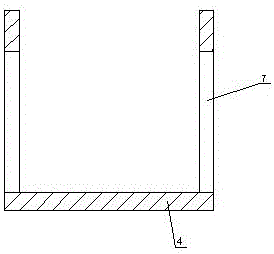
[0043] Such as Figure 8 ~ Figure 12 As shown, the difference between this embodiment and Embodiment 1 is that the height adjustment device includes an upper frame body 14 and a lower frame body 15, the upper end of the upper frame body 14 is fixedly connected with the bottom of the base 4, and the lower frame body 15 is sleeved on the lower part of the upper frame body 14 , two positioning bolt holes 16 are provided on the corresponding side walls of the lower frame body 15, and a number of adjusting bolt holes 17 matched with the positioning bolt holes 16 are arranged on the upper frame body 14 at intervals along its height direction, and a positioning bolt 18 After passing through the positioning bolt holes 16 and any adjusting bolt holes 17, the upper frame body 14 is connected with the lower frame body 15 through a positioning nut 19 . The bottom of the control switch 2 in the switch support seat 1 is provided with an adjusting gasket (not shown in the figure).

[0044] ...


PUM


Abstract

The invention relates to a block brake friction plate warning device. The block brake friction plate warning device comprises a switch supporting seat, and a control switch is arranged in the switch supporting seat. A button of the control switch extends out from the top of the switch supporting seat, two corresponding connecting bolt holes are formed in the two sides of the lower portion of the switch supporting seat. A base is sleeved with the lower portion of the switch supporting seat. A connecting bolt penetrates through the two connecting bolt holes in the switch supporting seat and the two side walls of the base and then enable the switch supporting seat and the base to be connected through a connecting nut, and a height adjustment device is arranged on the lower portion of the base. The block brake friction plate warning device is reasonable in structural design and convenient to use; and under the condition that the working state of an existing block brake is not changed, prompting and warning to the thickness and the opening and closing clearance limit index of a block brake friction plate are conducted, so that an operator can regulate opening and closing clearances or replace friction plates timely.

Description

technical field [0001] The invention relates to an alarm device for block brake friction plates. Background technique [0002] Block brakes are widely used in various fields such as lifting and transportation equipment, metallurgy, and mechanical transmission. Relying on the interaction between the device and the brake wheel to generate effective friction to ensure the short-term stop of the equipment from the running state, and reduce the time from the running speed to the static state as much as possible. Ensure safe and stable operation of equipment. [0003] The block brake realizes braking by converting its own spring tension into the friction force formed by the pressure on the brake wheel through the pull rod and the triangular plate. When the block brake is actually used, after the spring tension is adjusted to the allowable value, the opening and closing clearance of the brake is adjusted by adjusting the tie rod. With the continuous use of the block brake, the t...

Claims


Application Information

Patent Timeline
Patent Type & Authority Applications(China)
IPC IPC(8): F16D66/02
CPCF16D66/028F16D2066/003
Inventor 李玉杰张拥军李丙玉吕克单为春
Owner SHANDONG IRON & STEEL CO LTD
Why Eureka
Try Eureka