Pressure release device, control method and oil charging equipment explosionproof fire extinguishing protection system

A release device and oil-filled equipment technology, which is applied in valve devices, mechanical equipment, fire rescue, etc., can solve the problems of oil-filled equipment shock wave pressure, oil-filled equipment pressure increase, oil-filled equipment pressure rise slowly, etc., to achieve Good practicability, wide application range, and the effect of improving safety

Active Publication Date: 2016-12-07
BEIJING ZHONGRUIHE ELECTRICAL
View PDF6 Cites 4 Cited by
  • Summary
  • Abstract
  • Description
  • Claims
  • Application Information

AI Technical Summary

Problems solved by technology

[0004] The first type is a slight failure of the equipment, which causes static pressure inside the oil-filled equipment, and the internal pressure of the oil-filled equipment rises slowly;
[0005] The second type is a serious failure of the equipment, which causes shock and fluctuating pressure inside the oil-filled equipment, and the internal pressure of the oil-filled equipment increases rapidly and violently;
[0006] At present, there is no technology that can solve these two kinds of pressure changes at the same time. Therefore, oil-filled equipment is facing the danger of explosion or even fire; in addition, for the fire protection of oil-filled equipment, water spray, water spray, Foam, their function is to extinguish the oil-filled equipment after a fire occurs in the oil-filled equipment. These methods cannot fundamentally prevent the explosion and fire of the oil-filled equipment.

Method used


Image

  • Pressure release device, control method and oil charging equipment explosionproof fire extinguishing protection system
  • Pressure release device, control method and oil charging equipment explosionproof fire extinguishing protection system
  • Pressure release device, control method and oil charging equipment explosionproof fire extinguishing protection system

Examples


Embodiment Construction

[0030] It should be noted that like numerals and letters denote similar items in the following figures, therefore, once an item is defined in one figure, it does not require further definition and explanation in subsequent figures.

[0031] In the description of the present invention, it should be noted that the terms "center", "upper", "lower", "left", "right", "vertical", "horizontal", "inner", "outer" etc. The indicated orientation or positional relationship is based on the orientation or positional relationship shown in the drawings, or the orientation or positional relationship that is usually placed when the product of the invention is used, and is only for the convenience of describing the present invention and simplifying the description, rather than indicating or implying References to devices or elements must have a particular orientation, be constructed, and operate in a particular orientation and therefore should not be construed as limiting the invention. In addit...


PUM


Abstract

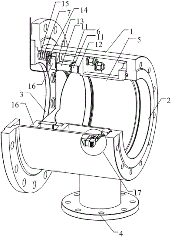
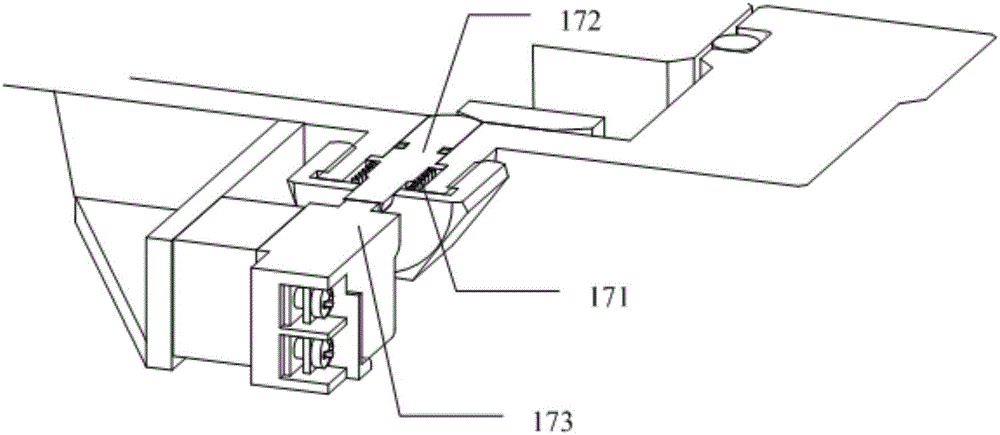
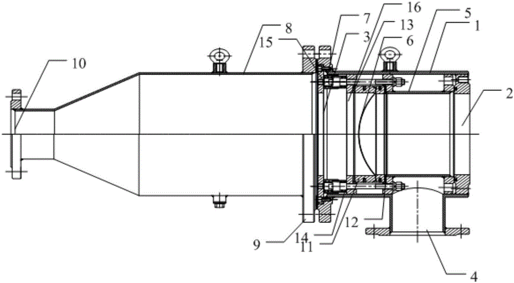
The invention provides a pressure release device, a control method and an oil charging equipment explosionproof fire extinguishing protection system. The pressure release device comprises a pressure reducing shell, a pressure release body and a signal switch; the pressure reducing shell includes an inlet, a main pressure release port and an auxiliary pressure release port; the inlet is connected with oil charging equipment; the main pressure release port and the auxiliary pressure release port are used for discharging pressure in the pressure reducing shell; the pressure release body is arranged in the pressure reducing shell, can open or close the main pressure release port along with slow change of internal pressure of the pressure reducing shell, and can open the auxiliary pressure release port along with rapid change of the internal pressure in the pressure reducing shell; and the signal switch is arranged on the pressure reducing shell for sending a pressure release signal according to actions of the pressure release body. The process can realize timely pressure release for various pressure changes generated in the oil charging equipment, guarantees safety and reliability of the oil charging equipment, and is higher in practicability and wide in application range.

Description

technical field [0001] The invention relates to the technical field of pressure safety, in particular to a pressure release device, a control method and an explosion-proof fire extinguishing protection system for oil-filled equipment. Background technique [0002] During the use of oil-filled equipment, there are faults such as overload and grounding. These faults are likely to cause the pressure inside the oil-filled equipment to increase, and in serious cases, there will be dangers of combustion and explosion. [0003] The internal pressure increase caused by the failure of oil-filled equipment can be divided into the following two situations, namely: [0004] The first type is a slight failure of the equipment, which causes static pressure inside the oil-filled equipment, and the internal pressure of the oil-filled equipment rises slowly; [0005] The second type is a serious failure of the equipment, which causes shock and fluctuating pressure inside the oil-filled equi...

Claims


Application Information

Patent Timeline
Patent Type & Authority Applications(China)
IPC IPC(8): F16K17/16F16K17/04F16K17/164A62C3/16A62C37/36A62C31/00
CPCA62C3/16A62C31/00A62C37/36F16K17/04F16K17/048F16K17/16F16K17/164
Inventor 朱述友
Owner BEIJING ZHONGRUIHE ELECTRICAL
Why Eureka
Try Eureka