Control method of heat pump system and heat pump system

A technology of a heat pump system and a control method, which is applied in the field of heat pumps, and can solve problems such as unguaranteed reliability of compressors, low superheat detection of supplementary air, and constant closing of supplementary air valves, etc., to ensure long-term reliable operation and simple control methods Reliable, accuracy-enhancing effects

Active Publication Date: 2016-12-07
GREE ELECTRIC APPLIANCES INC
View PDF6 Cites 25 Cited by
  • Summary
  • Abstract
  • Description
  • Claims
  • Application Information

AI Technical Summary

Problems solved by technology

Generally, the method of detecting the superheat of the supplementary air is used to distinguish whether there is liquid in the middle supplementary air, but this method is single-minded and has the following shortcomings: First, when the temperature-sensing package of supplementary air is placed behind the supplementary gas valve, due to the middle supplementary gas The valve has a certain throttling, which leads to a decrease in the detection temperature of the supplementary air, so that the detected superheat of the supplementary air is low and the supplementary air valve is often closed, resulting in the phenomenon that the supplementary air valve is often closed; In front of the valve, the detected air supply temperature is relatively high, and the superheat of the air supply is too high, resulting in the situation that it cannot be detected when a small amount of liquid is injected into the air, and the reliability of the compressor cannot be guaranteed.

Method used


Image

  • Control method of heat pump system and heat pump system
  • Control method of heat pump system and heat pump system
  • Control method of heat pump system and heat pump system

Examples


Embodiment Construction

[0047] In order to make the technical solution of the present invention clearer, the control method of the heat pump system and the heat pump system of the present invention will be further described in detail below in conjunction with the accompanying drawings. It should be understood that the specific embodiments described here are only used to explain the present invention and not to limit the present invention. It should be noted that, in the case of no conflict, the embodiments in the present application and the features in the embodiments can be combined with each other.

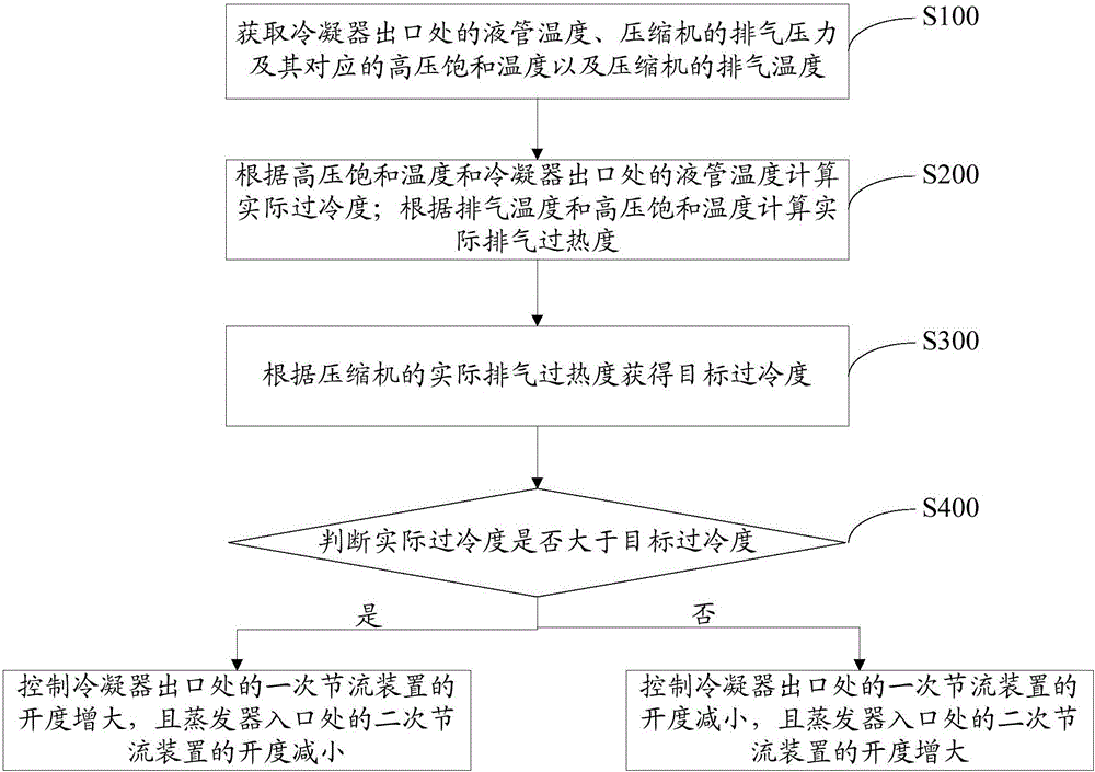
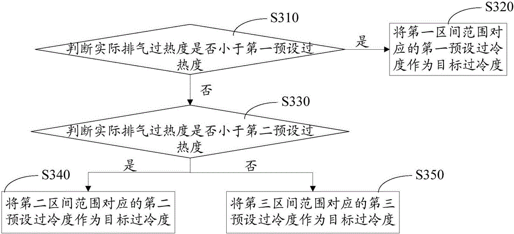
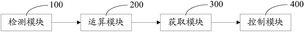
[0048] Such as figure 1 As shown, the control method of the heat pump system according to an embodiment of the present invention is used for the detection and judgment of the amount of supplemented air with liquid in the low-temperature heat pump system and the adjustment of the amount of supplemented air in the system, thereby improving the accuracy of the detection of the amount of supplemented air w...


PUM


Abstract

The invention provides a control method of a heat pump system. The control method comprises steps as follows: the liquid pipe temperature at an outlet of a condenser, the discharge pressure of a compressor, the high-pressure saturation temperature corresponding to the discharge pressure and the discharge temperature of the compressor are acquired; the actual super-cooling degree is calculated according to the high-pressure saturation temperature and the liquid pipe temperature at the outlet of the condenser; the actual discharge superheat degree is calculated according to the discharge temperature and the high-pressure saturation temperature; the target super-cooling degree is acquired according to the actual discharge superheat degree of the compressor; whether the actual super-cooling degree is larger than the target super-cooling degree or not is judged, and if the actual super-cooling degree is larger than the target super-cooling degree, the actual super-cooling degree is reduced by adjusting the opening degree of a throttling device; and if the actual super-cooling degree is not larger than the target super-cooling degree, the actual super-cooling degree is increased by adjusting the opening degree of the throttling device. The invention further provides the heat pump system. With the control method of the heat pump system and the heat pump system, the accuracy of gas filling liquid detection and judgment of the system is improved, and the compressor is prevented from producing liquid impact, so that long-time reliable running of the compressor can be guaranteed.

Description

technical field [0001] The invention relates to the technical field of heat pumps, in particular to a heat pump system control method and the heat pump system. Background technique [0002] In the air injection enthalpy system, the intermediate injection has a very important impact on the system performance and reliability. The liquid in the air injection will lead to the dilution of the lubricating oil in the compressor. When more liquid refrigerant enters the compressor cylinder at a higher speed, Due to the impact and incompressibility of the liquid, it will cause excessive bending or fracture of the suction valve plate, as well as severe wear and tear of the cylinder. Closing the middle air injection control valve can effectively avoid air injection with liquid, which is beneficial to the long-term operation of the compressor, but greatly reduces the performance of the two-stage compression system. [0003] Therefore, the middle air injection needs to be normally opened...

Claims


Application Information

Patent Timeline
Patent Type & Authority Applications(China)
IPC IPC(8): F25B49/02
CPCF25B49/02F25B2600/25F25B2700/1931F25B2700/21152F25B2700/21163
Inventor 谭锋梁尤轩赵桓
Owner GREE ELECTRIC APPLIANCES INC
Why Eureka
Try Eureka