Three-rocker type wall switch

A wall switch and rocker technology, which is applied to the parts of the flip switch/rocker switch, etc., can solve the problems of damage to the electrical circuit of the switch component, water leakage from the wall and the floor, etc.

Active Publication Date: 2016-12-07
常熟东南高新技术创业服务有限公司
5 Cites 0 Cited by

AI-Extracted Technical Summary

Problems solved by technology

[0003] Since the seesaw is movable, there must be a certain gap between the seesaw and the opening of the panel. When encountering a humid climate (such as "returning to the south" in southern China), th...

Method used

[0110] In this embodiment, the first groove on the first flange pressing part is "匸" shaped and has the same shape as the first flange pressing part, and the first groove on the second flange pressing part It is in the shape of "two" and h...

Abstract

The invention relates to a three-rocker type wall switch, comprising a panel, a first group of switch assembly, a second group of switch assembly and a third group of switch assembly. The first group of switch assembly comprises a first rocker. The second group of switch assembly comprises a second rocker. The third group of switch assembly comprises a third rocker. The wall switch also comprises a first sealing element which can deform after force is applied to the first sealing element, a first pressing frame, a second pressing frame, a third pressing frame and a fourth pressing frame. According to the wall switch, through arrangement of the first sealing element, a water retaining wall is formed, components such as the first group of switch assembly, the second group of switch assembly and electrical appliance circuits in a wall can be effectively protected and waterproof and dustproof functions are realized. Through design of the structure of the first sealing element, especially, the design of increasing a first cross rib and a second cross rib, the gaps reserved between the first rocker and the second rocker, and the second rocker and the third rocker can be effectively sheltered.

Application Domain

Tumbler/rocker switch details

Technology Topic

EngineeringRetaining wall +1

Image

  • Three-rocker type wall switch
  • Three-rocker type wall switch
  • Three-rocker type wall switch

Examples

  • Experimental program(13)

Example Embodiment

[0058] Embodiment one:
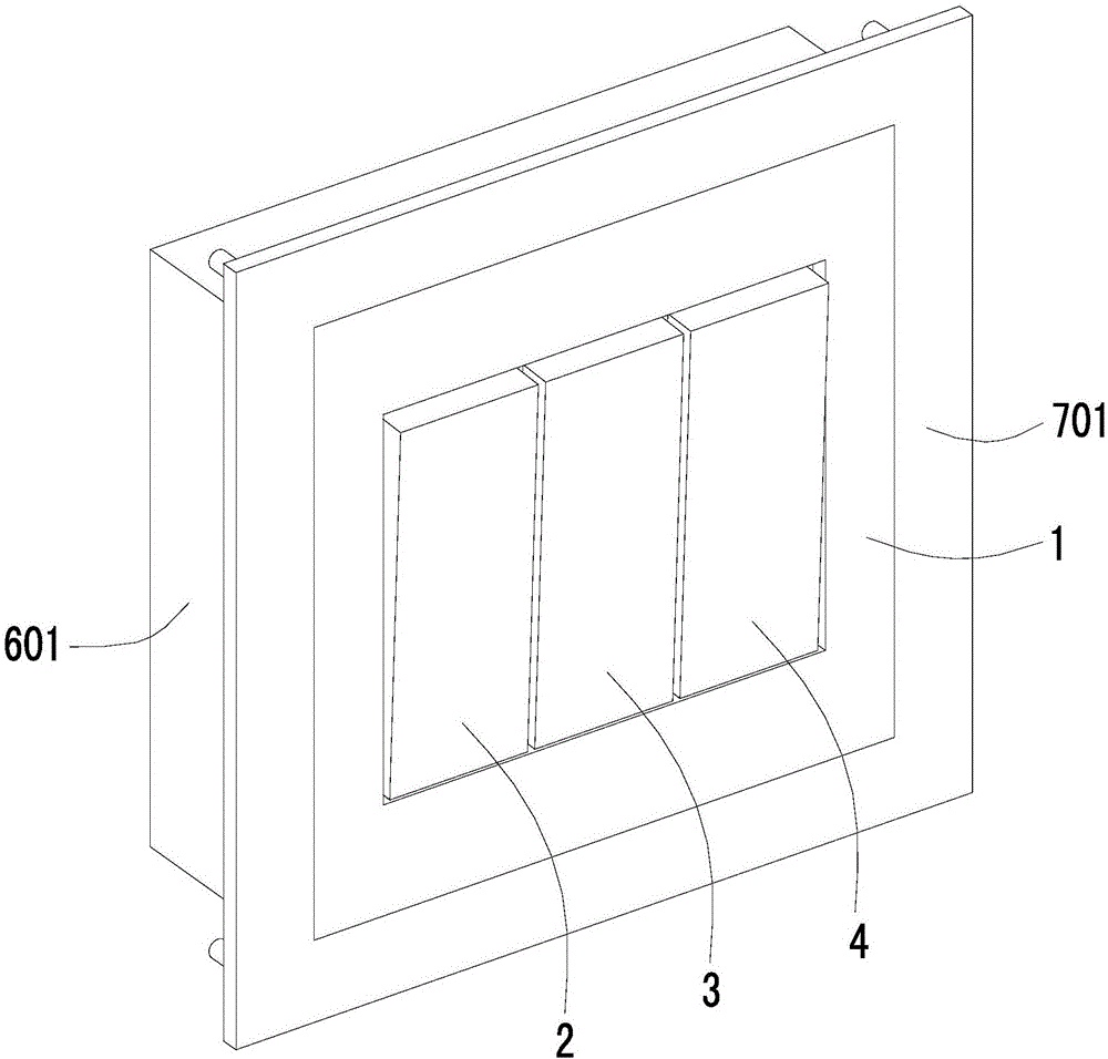
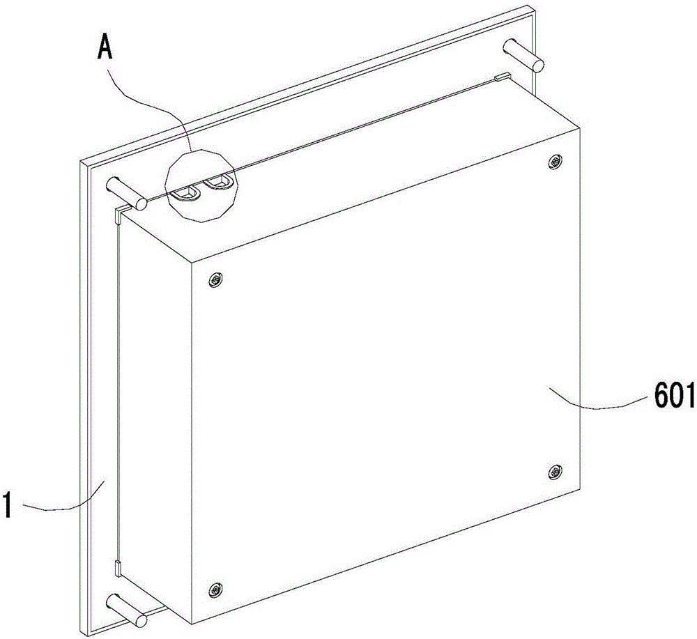
[0059] A three rocker type wall switch, comprising a panel 1 for fixing to the wall, a first group of switch components, a second group of switch components and a third group of switch components, the first group of switch components, the second group of switch components Both the group switch assembly and the third group switch assembly are installed on the panel 1, and the panel is provided with an opening 101, and the first group switch assembly includes a first seesaw 2 for controlling the opening and closing action of the first group switch assembly , the second set of switch assemblies includes a second seesaw 3 for controlling the opening and closing actions of the second set of switch assemblies, and the third set of switch assemblies includes a second rocker 3 for controlling the opening and closing actions of the third set of switch assemblies The third seesaw 4, the first seesaw 2, the second seesaw 3 and the third seesaw 4 are all exposed outside the panel through the opening 101 for people to press, the first seesaw 2, the second seesaw 3 and the third seesaw Three seesaws 4 are arranged side by side, between the first seesaw 2 and the opening 101, between the second seesaw 3 and the opening 101, between the third seesaw 4 and the opening 101, between the first seesaw 2 and the second seesaw 3, as well as between the second seesaw 3 and the third seesaw 4, a space 102 is left so that the first seesaw 2, the second seesaw 3 and the third seesaw 4 can move;
[0060] It also includes a deformable first sealing member 5, a first pressure frame 6, a second pressure frame 7, a third pressure frame 8 and a fourth pressure frame 9, the first pressure frame 6, The second press frame 7, the third press frame 8 and the fourth press frame 9 are all ring-shaped, especially the first press frame, the second press frame, the third press frame and the fourth press frame are all in the shape of a square ring;
[0061] The first sealing member 5 is in the shape of a "mesh" and includes an annular main body 51 and a first transverse rib 52 and a second transverse rib 53 across the hollow of the annular main body 51. The first transverse rib 52 The rib 52 is parallel to and spaced apart from the second transverse rib 53, and the first transverse rib 52 and the second transverse rib 53 divide the hollow of the annular body portion 51 into a first grid 54, a second grid 55 and a third grid. 56;
[0062] The first seesaw 2 is provided with a first seesaw flange 21 that is ring-shaped, especially square ring-shaped, and the second seesaw 3 is provided with a second seesaw flange 31 that is ring-shaped, especially square ring-shaped. The seesaw 4 is provided with a third seesaw flange 41 that is ring-shaped, especially square ring-shaped, and the panel 1 is provided with a ring-shaped, especially square ring-shaped panel flange 11. The first seesaw flange 21, the second seesaw flange Both the seesaw flange 31 and the third seesaw flange 41 are surrounded by the panel flange 11;
[0063] The outer edge portion of the annular main body portion 51 of the first sealing member is clamped between the fourth pressure frame 9 and the panel flange 11, and the edge portion surrounding the first grid 54 is clamped by the first pressure frame 6 Between the first seesaw flange 21, the edge that surrounds the second lattice 55 is clamped between the second pressure frame 7 and the second seesaw flange 31, and the edge that surrounds the third lattice 56 is clamped between the second press frame 7 and the second seesaw flange 31. Clamped between the third pressure frame 8 and the third seesaw flange 41 .
[0064] In this embodiment, the inner side of the annular body portion 51 of the first sealing element encloses the hollow of the annular body portion. In this embodiment, the structures of the first seesaw 2 , the second seesaw 3 and the third seesaw 4 are the same.
[0065] In this embodiment, the panel 1 has a front 12 facing people and a back 13 opposite to the front 12 when the panel is installed on the wall, the direction from the front 12 to the back 13 is toward the wall, and the panel flange 11 Located on the back side 13 of the panel and extending towards the wall, the panel flange 11 also surrounds the opening 101, the first seesaw flange 21 is arranged on the first seesaw 2 and also extends towards the wall, the second seesaw The flange 31 is disposed on the second rocker 3 and also extends toward the wall. The third rocker flange 41 is disposed on the third rocker 4 and also extends toward the wall.

Example Embodiment

[0066] Embodiment two:
[0067] A three-rocker wall switch that is easy to disassemble. This embodiment is a further limitation made on the basis of Embodiment 1. This embodiment includes all the structural features of Embodiment 1, and makes the following limitations:
[0068] The first pressure frame 6 is detachably locked on the first seesaw 2 through the first screw 60, the second pressure frame 7 is detachably locked on the second seesaw 3 through the second screw 70, and the third The pressure frame 8 is detachably locked on the third rocker 4 through the third screw 80, and the fourth pressure frame 9 is detachably locked on the panel 1 through the fourth screw 90, especially the fourth pressure frame 9 It is detachably locked on the back side 13 of the panel by a fourth screw 90 .

Example Embodiment

[0069] Embodiment three:
[0070] A three-saw type wall switch with double seals, this embodiment is further limited on the basis of embodiment 1 or embodiment 2, and this embodiment includes all the structural features of embodiment 1 or embodiment 2 , and make the following restrictions:
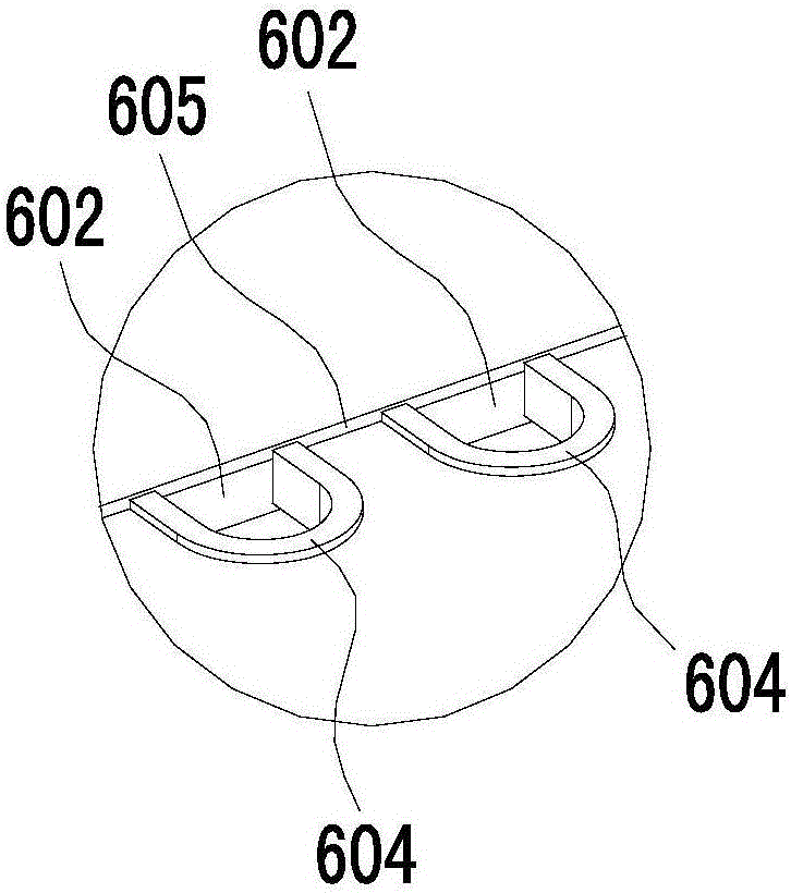
[0071] It also includes a deformable second seal 20 after being stressed. The second seal 20 is in the shape of a square ring and includes a first sealing edge 201, a second sealing edge 202, and a third sealing edge connected end to end in sequence. 203 and the fourth sealing edge portion 204, the opposite edge of the first sealing edge portion 201 is the third sealing edge portion 203, and the opposite edge of the second sealing edge portion 202 is the fourth sealing edge portion 204;
[0072] The fourth press frame 9 is in the shape of a square ring, comprising a first side portion 91 of the fourth press frame connected end to end, a second side portion 92 of the fourth press frame, a third side portion 93 of the fourth press frame and a fourth side portion of the fourth press frame. The fourth side portion 94 of the press frame, the opposite side of the first side portion 91 of the fourth press frame is the third side portion 93 of the fourth press frame, and the opposite side of the second side portion 92 of the fourth press frame is the fourth press frame. the fourth side portion 94 of the frame;
[0073] The structures of the first press frame 6 and the third press frame 8 are the same, and both include a first main body press portion 61 in the shape of a square ring and a first flange press portion 62 in the shape of a “cup”. In this embodiment, The first press frame 6 and the third press frame 8 are symmetrically distributed with the second press frame 7 as the center of symmetry;
[0074] The first main body pressing portion 61 includes a first main body side portion 611, a second main body side portion 612, a third main body side portion 613 and a fourth main body side portion 614 connected end to end in sequence, and the opposite side of the first main body side portion 611 is the second main body side portion 611. Three main body sides 613, the side opposite to the second main body side 612 is the fourth main body side 614;
[0075] The first flange pressing portion 62 includes a first flange portion 621 , a second flange portion 622 and a third flange portion 623 , and the opposite side of the first flange portion 621 is the third flange portion 623 , the tail end of the first flange edge portion 621 is connected to the head end of the second flange edge portion 622, and the tail end of the second flange edge portion 622 is connected to the head end of the third flange edge portion 623;
[0076] The first flange 621 extends outward from the first main body 611 , the second flange 622 extends outward from the second main body 612 , and the third flange 623 extends from the third main body 613 extend outward;
[0077] The second pressure frame 7 includes a second main body pressure portion 71 in a square ring shape and a second flange pressure portion 72 in a “two” shape;
[0078] The second main body pressure portion 71 includes a fifth main body edge portion 711, a sixth main body edge portion 712, a seventh main body edge portion 713 and an eighth main body edge portion 714 connected end to end in sequence, and the opposite side of the fifth main body edge portion 711 is the second main body edge portion 711. Seven main body sides 713, the opposite side of the sixth main body side 712 is the eighth main body side 714;
[0079] The second flange pressing portion 72 includes a fourth flange portion 721 and a fifth flange portion 722, and the opposite side of the fourth flange portion 721 is the fifth flange portion 722;
[0080] The fourth flange edge 721 extends outward from the fifth body edge 711 , and the fifth flange edge 722 extends outward from the seventh body edge 713 ;
[0081] The second seesaw 3 is located between the first seesaw 2 and the third seesaw 4, the second press frame 7 is located between the first press frame 6 and the third press frame 8, and the second grid 55 is located between the first grid 54 and the third press frame 8. Between the 3rd grid 56, the 4th main body edge portion 614 of the first press frame is facing the 8th main body edge portion 714 of the second press frame and leaves a certain interval between them, the second press frame The sixth main body edge 712 is facing the fourth main body edge 614 of the third pressure frame with a certain distance between them;
[0082] The first flange portion 621 of the first pressure frame, the fourth flange portion 721 of the second pressure frame and the first flange portion 621 of the third pressure frame are collinear, but the first pressure frame Between the first flange portion 621 of the second pressure frame and the fourth flange portion 721 of the second pressure frame, between the fourth flange portion 721 of the second pressure frame and the first flange portion 621 of the third pressure frame There is a certain interval between them, and the first flange edge portion 621 of the first pressure frame, the fourth flange edge portion 721 of the second pressure frame and the first flange edge portion 621 of the third pressure frame are all pressed on the second pressure frame. On the first sealing edge portion 201 of the second sealing member, the first sealing edge portion 201 of the second sealing member is pressed on the first edge portion 91 of the fourth pressure frame;
[0083] The second flange portion 622 of the first pressure frame presses on the second sealing edge portion 202 of the second sealing member, and the second sealing edge portion 202 of the second sealing member presses on the second edge portion 92 of the fourth pressing frame superior;
[0084] The third flange portion 623 of the first pressure frame, the fifth flange portion 722 of the second pressure frame and the third flange portion 623 of the third pressure frame are collinear, but the first pressure frame Between the third flange portion 623 of the second pressure frame and the fifth flange portion 722 of the second pressure frame, between the fifth flange portion 722 of the second pressure frame and the third flange portion 623 of the third pressure frame There is a certain interval between them, and the third flange edge portion 623 of the first pressure frame, the fifth flange edge portion 722 of the second pressure frame and the third flange edge portion 623 of the third pressure frame are all pressed on the third flange edge portion 623 of the third pressure frame. On the third sealing edge portion 203 of the second sealing member, the third sealing edge portion 203 of the second sealing member is pressed on the third edge portion 93 of the fourth pressure frame;
[0085] The second flange portion 622 of the third pressure frame presses on the fourth sealing edge portion 204 of the second sealing member, and the fourth sealing edge portion 204 of the second sealing member presses on the fourth edge portion 94 of the fourth pressing frame superior.
[0086] In this embodiment, along the direction toward the wall, the first flange pressing portion 62 of the first pressure frame, the second flange pressing portion 72 of the second pressure frame and the first flange pressing portion 62 of the third pressure frame are all located at The front of the fourth pressure frame 9, so that the second seal 20 is clamped on the first flange pressure part 62 of the first pressure frame, the second flange pressure part 72 of the second pressure frame and the third pressure frame between the first flange pressing portion 62 and the fourth pressing frame 9 .

PUM

no PUM

Description & Claims & Application Information

We can also present the details of the Description, Claims and Application information to help users get a comprehensive understanding of the technical details of the patent, such as background art, summary of invention, brief description of drawings, description of embodiments, and other original content. On the other hand, users can also determine the specific scope of protection of the technology through the list of claims; as well as understand the changes in the life cycle of the technology with the presentation of the patent timeline. Login to view more.
Why Eureka
Try Eureka