Light guide plate pouring gate cold-cutting machine for cutting step by step and cold-cutting method thereof

A light guide plate and gate technology, which is applied to the step-by-step cutting light guide plate gate cold cutting machine and its cold cutting field, can solve the problems of unguaranteed quality, increased enterprise cost, and high labor intensity, and reduce damage to the guide rail plate The possibility of improving processing efficiency and ensuring the effect of cutting quality

Active Publication Date: 2016-04-20
SUZHOU TA&A ULTRA CLEAN TECH CO LTD
View PDF10 Cites 10 Cited by
  • Summary
  • Abstract
  • Description
  • Claims
  • Application Information

AI Technical Summary

Problems solved by technology

[0004] Existing gate cutting methods, one is manual cutting one by one with a cutter, but this method is labor-intensive, high labor cost, work efficiency, and the quality of cutting is affected by personal subjective factors and actual operation, and the quality cannot be guaranteed
[0005] Another method is to use a cutting device with one mold and two cavities to separate two molded parts from the gate at one time. However, since the workpiece to be processed is manually positioned by hydraulic pressure in a jig with one mold and two cavities, the efficiency is slow and cannot be guaranteed. Accuracy of positioning; at the same time, when both sides are cut at the same time, both cutting knives will generate tensile stress on the middle forming nozzle of the light guide plate, causing it to shrink and pull up indefinitely, thereby deforming the cut area of ​​the light guide plate , seriously affecting the quality of the final product
[0006] In addition, some high-tech companies use heated cutting tools and then polish them to meet the requirements of smooth cutting. However, this method is cumbersome. The cutting adopts the principle of hot melting, which is easy to draw and the polishing process is easy to produce debris, which affects the light guide plate. performance, further, the price of this cutting equipment is high, which increases the cost of the enterprise

Method used


Image

  • Light guide plate pouring gate cold-cutting machine for cutting step by step and cold-cutting method thereof
  • Light guide plate pouring gate cold-cutting machine for cutting step by step and cold-cutting method thereof
  • Light guide plate pouring gate cold-cutting machine for cutting step by step and cold-cutting method thereof

Examples


Embodiment 2

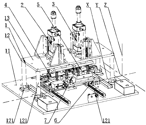
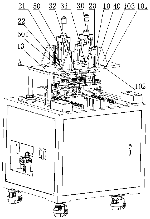
[0072] The overall structure of this embodiment is similar to that of Embodiment 1, and the difference is that: the bearing plates 41 of the first vacuum positioning jig 4 and the second vacuum positioning jig 5 are respectively provided with limiting holes 411, and the installation The bottom of the plate 40 is respectively provided with positioning posts 60 matching the limiting holes 411, and the number of the limiting holes 411 and the positioning posts 60 are four respectively.

[0073] The overall process of this embodiment is similar to that of Embodiment 1, the difference is that when the driving cylinder 50 pushes the mounting plate 40 down, the positioning column 60 moves down at the same time, and is inserted into the bearing The positioning hole 411 on the plate 41 ensures accurate positioning of the first cutting device 2 and the first vacuum positioning jig 4 as well as the second cutting device 3 and the second vacuum positioning jig 5 .

Embodiment 1

[0075] The overall mechanism of embodiment 1 is similar to that of embodiments 1 and 2, and the difference is that: the bottoms of the two mounting plates 40 are respectively equipped with lower pressing plates 70, and one edge of the two lower pressing plates 70 is respectively connected to the first The cutting point positions of the cutting knife 22 and the second cutting knife 32 on the workpiece 8 correspond, and the main bodies of the two lower pressing plates 70 are respectively pressed on the first vacuum positioning jig 4 and the second vacuum positioning jig 4 and the second vacuum positioning jig 4 . Position the molded part in jig 5.

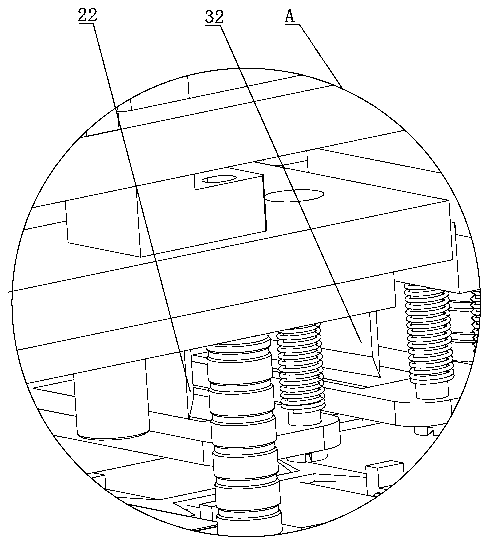
[0076] The lower pressing plate 70 is provided with at least three through holes, and a sliding bar 80 is inserted in the three through holes, and the lower pressing plate 70 can slide up and down along the sliding bar 80, and the sliding bar 80 The jacket is provided with a spring 90 , the upper end of the spring 90 is affixed to th...


PUM


Abstract

The invention discloses a light guide plate pouring gate cold-cutting machine for cutting step by step and a cold-cutting method thereof. The light guide plate pouring gate cold-cutting machine comprises a stander, wherein a first cutting device and a second cutting device are arranged on the stander; a first vacuum positioning jig is arranged below the first cutting device; a second vacuum positioning jig is arranged below the second cutting device; a supporting table keeping clearances from the first vacuum positioning jig and the second vacuum positioning jig is arranged between the first vacuum positioning jig and the second vacuum positioning jig; in a normal state, the supporting table, the first vacuum positioning jig and the second vacuum positioning jig are combined into a placing trough for holding a workpiece to be processed, and the first vacuum positioning jig and / or the second vacuum positioning jig can move along the X-axial direction; the first vacuum positioning jig and the second vacuum positioning jig are arranged on a Y-axial moving mechanism. The light guide plate pouring gate cold-cutting machine can automatically position the workpiece to be processed and guarantee the precision of a cutting position; meanwhile, cutting step by step ensures the cutting quality; furthermore, the whole process is automatic, and the automation degree is high, so that the processing efficiency is greatly improved, and the labor cost of an enterprise is reduced.

Description

technical field [0001] The invention relates to a cold cutting machine and a cold cutting method thereof, in particular to a step-by-step cold cutting machine for a gate of a light guide plate and a cold cutting method thereof. Background technique [0002] At present, the small-sized light guide plate (light guide plate) is made of optical grade acrylic / PC plastic particles, hot-melt injection molding, and the processed dots of the mold core are transferred to the dot surface of the light guide plate. The surface-specific dot structure is used to distribute the transmitted light evenly on the entire surface through light transmission characteristics such as reflection and refraction. Using the structural design of the mold, the ultra-thin light guide plate can be injection-molded, combined with advanced technologies such as mold core dot processing, V-CUT processing, etc., to make the light spread more fully, and reasonable use can be processed on the basis of ultra-thin, u...

Claims


Application Information

Patent Timeline
Patent Type & Authority Applications(China)
IPC IPC(8): B29C45/38
CPCB29C45/382
Inventor 刘金华
Owner SUZHOU TA&A ULTRA CLEAN TECH CO LTD
Why Eureka
Try Eureka