A power cable connection device

A technology for connecting equipment and power cables, applied in the field of power cable connecting equipment, can solve the problems of inconvenient maintenance, confusion of lines, intertwining of cables, etc., and achieve the effect of convenient classification and connection and improving connection efficiency.

Inactive Publication Date: 2017-10-03
PENGLAI POWER SUPPLY CO OF STATE GRID SHANDONG ELECTRIC POWER CO
View PDF3 Cites 0 Cited by
  • Summary
  • Abstract
  • Description
  • Claims
  • Application Information

AI Technical Summary

Problems solved by technology

[0002] Cable connections usually use adapters. Since adapters are usually metal structures, adjacent adapters are separated from each other by an insulating layer. Adjacent cables often entangle with each other, resulting in confusing lines and inconvenient wiring. Maintenance, where problems with some of the cables usually require complete replacement

Method used


Image

  • A power cable connection device
  • A power cable connection device
  • A power cable connection device

Examples


Embodiment 1

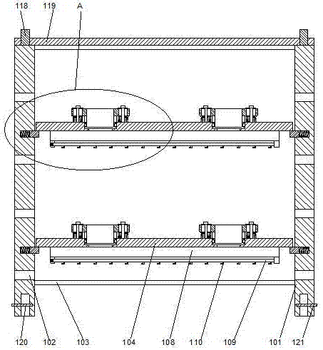
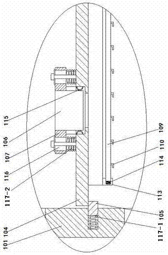
[0022] like Figure 1-3 As shown, a power cable connection device includes a bracket formed by two side bars 101, and wire holes 102 are respectively arranged on the side bars 101, and the upper and lower ends of the two side bars 101 respectively pass through The crossbeams 103 are connected to each other, a lifting plate 104 is arranged between the two side bars 101, a support block 105 is respectively arranged on the two side bars 101, and the two side bars 101 facing each other Counterbores arranged at intervals are respectively arranged on the end faces, and first compression springs 117-1 are respectively provided inside the counterbores, and one end of the support block 105 is inserted into the inner side of the counterbore, and the first compression spring 117-1 Under the natural state of a compression spring 117-1, the support block 105 partially protrudes from the outside of the counterbore, and the lower end surface of the lifting plate 104 is attached to the upper ...

Embodiment 2

[0026] In this embodiment, in order to avoid disconnection of the connection structure when the circuit adapter board is subjected to an external force, preferably, elastic metal sheets 115 are respectively arranged on the inner walls of the installation grooves, and the elastic metal sheets 115 are facing toward the middle. The circuit adapter board 106 is a bar-shaped structure that is arched in the direction. Using the elastic metal sheet structure, the circuit adapter board is suspended relative to the installation groove. When the lifting plate is subjected to external force, under the buffering action of the elastic metal sheet, the force on the circuit adapter board can be greatly reduced, so that It is not easily damaged.

[0027] In order to enable the lifting board to move relative to the circuit adapter board, in this embodiment, preferably, the fixing ear 107 is provided with a bar-shaped hole 116, and the fixing ear 107 passes through the bar-shaped hole 116. Bol...

Embodiment 3

[0031]In this embodiment, in order to facilitate the protection of the cable adapter plate, in this embodiment, preferably, a stud 118 is provided on the upper end surface of the side bar 101, and an end is provided above the side bar 101. For the cover 119, the studs 118 penetrate through the end cover 119 and are fixed by nuts. Using the end cap structure, the circuit adapter board is placed under the end cap to avoid open circuit when it is collided.

[0032] In this embodiment, a concave hole 120 corresponding to the position of the stud 118 is provided on the lower end surface of the side bar 101 . Use the concave holes provided on the side bars to align the two support structures longitudinally with each other, align the concave holes on the upper side bars and the studs on the lower side bars with each other, so that the The stud is inserted into the concave hole on the upper side strip to realize the stacking of the upper and lower brackets.

[0033] In this embodime...


PUM


Abstract

The invention discloses electric power cable connecting equipment. The electric power cable connecting equipment comprises a bracket formed by two edge strips, wherein line-passing holes are formed in the edge strips respectively; the upper and lower ends of the two edge strips are connected through cross beams; lifting plates are arranged between the two edge strips; the two edge strips are provided with supporting blocks respectively; counter bores which are arranged at intervals are formed in the opposite end planes of the two edge strips respectively; compression springs are arranged on the inner sides of the counter bores respectively; one ends of the supporting blocks are inserted in the inner sides of the counter bores; the supporting blocks partially extend out of the outer sides of the counter bores in the natural states of the compression springs; the lower end planes of the lifting plates are attached to the upper end planes of the supporting blocks; mounting grooves are formed in the lifting plates; and circuit transfer boards are arranged in the mounting grooves. According to the electric power cable connecting equipment, the circuit is connected through the circuit transfer boards, so that the connection of the electric power cable becomes convenient; the concentrated connection of the multiple cables can be realized; and the maintenance and the operation are convenient.

Description

technical field [0001] The invention relates to a power cable connection device. Background technique [0002] Cable connections usually use adapters. Since adapters are usually metal structures, adjacent adapters are separated from each other by an insulating layer. Adjacent cables often entangle with each other, resulting in confusing lines and inconvenient connections. Maintenance, when something goes wrong with some of these cables usually requires a complete replacement. Contents of the invention [0003] The purpose of the present invention is to provide a power cable connection device, which can improve the problems existing in the prior art. By using a circuit adapter board to connect the circuit, the connection of the power cable is facilitated, and the centralized connection of multiple cables can be realized. Easy maintenance operation. [0004] The present invention is realized through the following technical solutions: [0005] A power cable connection devi...

Claims


Application Information

Patent Timeline
Patent Type & Authority Patents(China)
IPC IPC(8): H02G1/14
CPCH02G1/14
Inventor 姚伟周进刘亨琪王作军姜辉李启建张立永姜永恒时德剑田吉青金风雷徐永军郭明磊吴新鹏张建利万海朝王雪奇靳庆路李扬
Owner PENGLAI POWER SUPPLY CO OF STATE GRID SHANDONG ELECTRIC POWER CO
Why Eureka
Try Eureka