
Novel liquid soap pump

A soap liquid, a new type of technology, applied in home appliances, sanitary equipment, applications, etc., can solve the problems of glass balls being easily stuck on the spring, soap liquid pump damage, etc., and achieve the effect of simple and reliable structure and long service life

Inactive Publication Date: 2016-12-14
JIANGMEN AYT ELECTRICAL APPLIANCE CO LTD
View PDF5 Cites 4 Cited by
  • Summary
  • Abstract
  • Description
  • Claims
  • Application Information

AI Technical Summary

Problems solved by technology

[0002] Existing soap liquid pump structure mainly comprises press head, body, main column, secondary column, piston bushing, suction pipe, spring and glass ball, and glass ball is positioned at the top of described suction pipe and seals the top of described suction pipe, this structure When in use, the glass ball is easy to get stuck on the spring, resulting in damage to the soap dispenser pump

Method used


Image

  • Novel liquid soap pump

Examples


Embodiment Construction

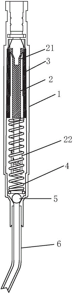
[0009] refer to figure 1 , a new type of soap liquid pump of the present invention, comprising a body 1 and a main column 2 installed in the body 1, a piston sleeve 3, a spring 4, and a glass ball 5, the bottom end of the body 1 is connected with a suction pipe 6, the The piston sleeve 3 is set on the outside of the main column 2 and can move up and down along the inner wall of the main body 1. The lower part of the main body 1 is provided with a constriction port for supporting the glass ball 5, and the glass ball 5 is located on the constriction port. An elastic bayonet 21 stuck in the piston sleeve 3 is provided, and the lower part of the main column 2 is provided with an outer expansion part 22 for fixing the spring 4 , and the outer expansion part 22 is suspended above the glass bulb 6 .

[0010] The inner wall of the piston sleeve 3 is provided with a protrusion that cooperates with the elastic bayonet 21 of the main column 2 .

[0011] In the novel soap liquid pump of ...


PUM


Abstract

The invention discloses a novel liquid soap pump which comprises a body, a main column, a piston sleeve, a spring and a glass ball, wherein the main column, the piston sleeve, the spring and the glass ball are mounted in the body. A straw is connected at the bottom end of the body, the piston sleeve is mounted on the outer side of the main column in a sleeving manner and can vertically move along the inner wall of the body, a constriction opening for supporting the glass ball is formed in the lower portion of the body, the glass ball is positioned at the constriction opening, an elastic bayonet clamped in the piston sleeve is arranged at the top end of the main column, an external expansion portion for fixing the spring is arranged on the lower portion of the main column and erected above the glass ball, the main column is provided with the external expansion portion erected below the glass ball, a one-way valve structure is formed between the main column and the glass ball, liquid can only enter the body from the straw, the glass ball can recover to a normal position to plug the straw along with the liquid once the liquid flows backwards, a one-way function is achieved, the main column fixes the spring through the external expansion portion, vertical motion of the glass ball cannot be affected by the spring, and the folding position of the spring is guided.

Description

technical field [0001] The present invention relates to a soap liquid pump. Background technique [0002] Existing soap liquid pump structure mainly comprises press head, body, main column, secondary column, piston bushing, suction pipe, spring and glass ball, and glass ball is positioned at the top of described suction pipe and seals the top of described suction pipe, this structure When in use, the glass bulb is easy to get stuck on the spring, causing damage to the soap dispenser pump. Contents of the invention [0003] The invention provides a novel soap liquid pump, which solves the problem that the glass ball is easily stuck on the spring. [0004] The technical scheme that the present invention adopts for solving its technical problem is: [0005] A new type of soap liquid pump, including a body and a main column installed in the body, a piston sleeve, a spring, and a glass ball. The bottom end of the body is connected with a suction pipe. The inner wall moves up...

Claims


Application Information

Patent Timeline
Patent Type & Authority Applications(China)
IPC IPC(8): A47K5/12
CPCA47K5/1211
Inventor 雷志威梁和瑞区棋就何宝婷
Owner JIANGMEN AYT ELECTRICAL APPLIANCE CO LTD
Features
  • Generate Ideas
  • Intellectual Property
  • Life Sciences
  • Materials
  • Tech Scout
  • Unparalleled Data Quality
  • Higher Quality Content
  • 60% Fewer Hallucinations
Learn More