Micro-fluid chip based on dielectrophoresis effect

A microfluidic chip and microfluidic technology, applied in fluid controllers, laboratory containers, laboratory utensils, etc., can solve problems such as difficult operation

Active Publication Date: 2016-12-14
DALIAN UNIV OF TECH
View PDF5 Cites 10 Cited by
  • Summary
  • Abstract
  • Description
  • Claims
  • Application Information

AI Technical Summary

Problems solved by technology

In biological and chemical experiments, it is often necessary to observe and manipulate liquid droplets, biological cells, and other particles. However, due to the ...

Method used


Image

  • Micro-fluid chip based on dielectrophoresis effect
  • Micro-fluid chip based on dielectrophoresis effect
  • Micro-fluid chip based on dielectrophoresis effect

Examples


Embodiment 1

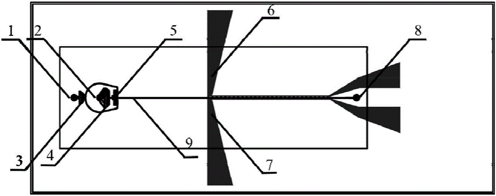
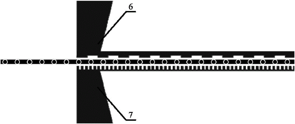
[0043] Such as figure 1 As shown, a microfluidic chip based on dielectrophoresis, including an ITO conductive glass substrate 10 and a PDMS main structure arranged on it and bonded thereto, the PDMS main structure includes a microfluidic chip for fluid flow. Pipeline 9, on the ITO conductive glass substrate 10, ITO conductive electrode I6 and ITO conductive electrode II7 are oppositely arranged on the outside of said microfluidic pipeline 9; one continuous phase fluid inlet 1; one receiving the fluid from the continuous phase fluid inlet 1 A continuous phase fluid filtering section 3; a discrete phase fluid inlet 2; a discrete phase fluid filtering section 4 receiving fluid from the discrete phase fluid inlet 2; receiving fluid from the continuous phase fluid filtering section 3 and the discrete phase fluid filtering section 4 The fluid rectification buffer area 5 ; the microfluidic pipeline 9 receives the fluid from the fluid rectification buffer area 5 and the fluid outlet 8...

Embodiment 2

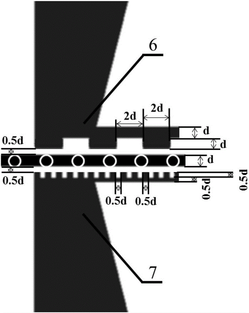
[0049] This embodiment is similar to the chip structure in Embodiment 1, but the size of the microfluidic channel 9 and the electrode size are adjusted. Wherein, the width of the microfluidic pipeline is 70 μm; the side of the electrode 16 close to the microfluidic pipeline 9 is in the shape of a square wave, and the other side is in the shape of a continuous strip; wherein, the width of the square wave is 140 μm, and the height of the square wave is 70 μm, the height of the continuous band is 70 μm, and the distance between the electrode I6 and the wall of the microfluidic pipeline 9 is 70 μm; the side of the electrode II7 close to the microfluidic pipeline 9 is in the shape of a square wave, and the other side is in the shape of a continuous strip; , the width of the square wave is 35 μm, the height of the square wave is 35 μm, the height of the continuous band is 35 μm, and the distance between the electrode II7 and the wall of the microfluidic pipeline 9 is 35 μm.

[0050]...


PUM


Abstract

The invention relates to a micro-fluid chip for decelerating fluid like droplets, cells and the like on the basis of the dielectrophoresis effect, and belongs to the technical field of micro-fluid chips. The micro-fluid chip comprises a substrate and a body structure arranged on and bonded with the substrate. The body structure comprises a micro-fluid pipeline for fluid circulating. An electrode I and an electrode II which are oppositely arranged are arranged outside the micro-fluid pipeline and on the substrate. The sides, close to the micro-fluid pipeline, of the electrode I and the electrode II are each in a square wave shape, and the other sides are each in a continuous belt shape. The micro-fluid chip has the advantages that the electrodes with special effects are added outside an existing micro-fluid conveying pipeline, due to the design of the electrodes, the aim of controlling the movements of droplets, cells and the like is achieved, more importantly, the electrodes are arranged on the two sides of a micro-fluid channel and do not extend into the micro-fluid channel, and through an active control method, damage-free control over single-dispersed droplets, biomolecules and molecules is achieved.

Description

technical field [0001] The invention relates to a microfluidic chip based on dielectrophoresis, in particular to a microfluidic chip that decelerates fluids such as liquid droplets and cells based on dielectrophoresis, and belongs to the technical field of microfluidic chips. Background technique [0002] A microfluidic chip is an integrated solid element based on semiconductor technology, which can perform precise and complex operations on microfluidic fluids. Since its flow rate can be controlled in the order of microliters to nanoliters, it is applied to the transmission of microfluidics. Sensing, transportation, detection and control, and because of its small size, it can effectively reduce the cost of the experiment and improve the efficiency of the experiment, so the microfluidic system has been well applied in medical and biological analysis experiments. [0003] The deceleration microfluidic chip technology can be applied to: realize the non-damage control of monodis...

Claims


Application Information

Patent Timeline
IPC IPC(8): B01L3/00
CPCB01L3/502707B01L3/50273B01L2300/0809B01L2400/0424
Inventor 闫英郭丹温诗铸
Owner DALIAN UNIV OF TECH
Why Eureka
Try Eureka