Integrated electromechanical lock

A lock head and electromechanical technology, applied in the field of locks, can solve the problems of inconvenient use, uncompact structure of locks, inability to directly drive the lock head, etc., and achieve the effect of avoiding the transmission mechanism

Inactive Publication Date: 2016-12-14
HANGZHOU LIUFU INTELLIGENT TECH CO LTD
View PDF4 Cites 4 Cited by
  • Summary
  • Abstract
  • Description
  • Claims
  • Application Information

AI Technical Summary

Problems solved by technology

[0003] The lock head of the existing mechanical lock can only be driven by the key to turn the dial, which is inconvenient to use. However, the motor of the electric lock is installed on the panel and cannot directly drive the lock head. The motor of the electric lock needs a more complicated transmission mechanism for transmission. , resulting in a lock structure that is not compact

Method used


Image

  • Integrated electromechanical lock
  • Integrated electromechanical lock
  • Integrated electromechanical lock

Examples


Embodiment 1

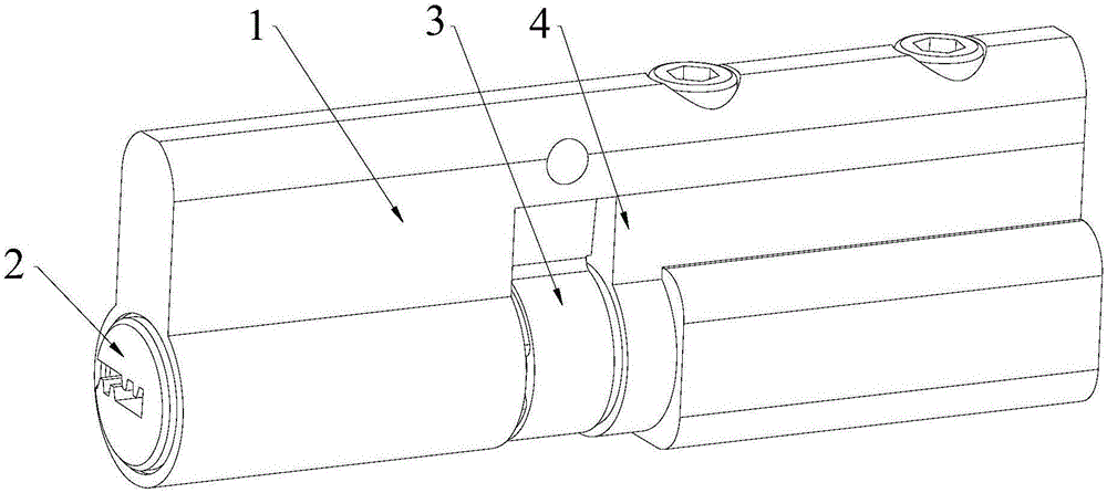
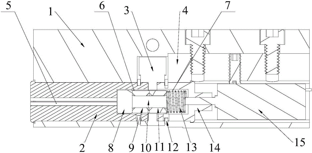
[0044] Such as figure 1 , 2 , 3 and 4, an electromechanical integrated lock, including:

[0045] lock case 1;

[0046] The first lock cylinder 2 is rotatably mounted on the lock case 1, one end of the first lock cylinder 2 has a first groove 6, and the other end has a keyhole 5;

[0047] The second lock cylinder 14 is rotatably mounted on the lock housing 1. One end of the second lock cylinder 14 has a second groove 7, and the other end has a motor drive hole 24. The second groove 7 is arranged opposite to the first groove 6. ;

[0048] The lock dial 3 is arranged between the first lock cylinder 2 and the second lock cylinder 14, and the lock cylinder 3 has a through hole;

[0049] The first clutch part 9 is slidably matched with the first lock cylinder 2, and the first clutch part 9 and the first lock cylinder 2 are relatively fixed in the circumferential direction. , and the first clutch part 9 has a first working position and a second working position. When the first c...

Embodiment 2

[0065] Such as Image 6 As shown, the difference between this embodiment and Embodiment 1 is that the lock shifting block 3 is a gear, and the through hole is arranged in the middle of the gear.

Embodiment 3

[0067] Such as Figure 7 As shown, the difference between this embodiment and Embodiment 1 is that the motor 15 is a transverse motor.


PUM


Abstract

The invention discloses an integrated electromechanical lock. The integrated electromechanical lock comprises a lock shell, a first lock cylinder, a second lock cylinder, a lock shifting block, a first clutch part, a second clutch part, a clutch shaft, a reset spring and a motor, wherein the first lock cylinder and the second lock cylinder are relatively arranged; the lock shifting block is arranged between the first lock cylinder and the second lock cylinder; one end of the first clutch part and the first lock cylinder are relatively fixed in the circumferential direction; the other end of the first clutch part is matched with the lock shifting block; one end of the second clutch part and the second lock cylinder are relatively fixed in the circumferential direction; the other end of the second clutch part is matched with the lock shifting block; the clutch shaft is inserted on the first clutch part and the second clutch part; the first clutch part and the second clutch part are rotatably mounted on the clutch shaft; and the motor is used for driving the second lock cylinder to rotate. According to the integrated electromechanical lock, the motor is directly matched with the second lock cylinder, and can drive the second lock cylinder and the second clutch part to rotate during operation, the second clutch part can drive the lock shifting block to rotate, a complex transmission mechanism is avoided through the structural form, the motor controls the shifting block to rotate directly through the second clutch part, and the entire structure is compact.

Description

technical field [0001] The invention relates to a lockset, in particular to an electromechanical integrated lock head. Background technique [0002] A lock refers to a device that acts as a seal, including locks, keys and accessories, and is generally interpreted as "a seal that must be unlocked with a key." [0003] The lock head of the existing mechanical lock can only be rotated by the key to drive the dial, which is inconvenient to use. However, the motor of the electric lock is installed on the panel and cannot directly drive the lock head. The motor of the electric lock needs a more complicated transmission mechanism for transmission. , resulting in a lock structure that is not compact. Contents of the invention [0004] Aiming at the above problems, the present invention proposes an electromechanical integrated lock head. [0005] The technical scheme that the present invention takes is as follows: [0006] An electromechanical integrated lock head, comprising: ...

Claims


Application Information

Patent Timeline
Patent Type & Authority Applications(China)
IPC IPC(8): E05B47/00E05B15/00
CPCE05B47/0012E05B2047/0026
Inventor 肖钧
Owner HANGZHOU LIUFU INTELLIGENT TECH CO LTD
Why Eureka
Try Eureka