Supercharge Your Innovation With Domain-Expert AI Agents!

Reducer with pin shaft hoisting

A technology of reducer and pin shaft, which is applied in the direction of load hanging components, components with teeth, transmission boxes, etc., which can solve the problem that the reducer cannot be lifted quickly, and achieve the effect of fast lifting and meeting the use requirements

Inactive Publication Date: 2016-12-14
CHANGZHOU XINER SPEED REDUCER
View PDF5 Cites 0 Cited by
  • Summary
  • Abstract
  • Description
  • Claims
  • Application Information

AI Technical Summary

Problems solved by technology

[0003] In order to overcome the deficiency that the existing reducer cannot be lifted quickly, the present invention provides a reducer that can be hoisted by a pin shaft

Method used


Image

  • Reducer with pin shaft hoisting

Examples


Embodiment Construction

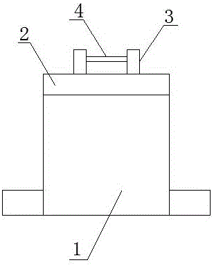
[0009] Such as figure 1 It is a structural schematic diagram of the present invention, a reducer hoisted by a pin shaft, including a body 1, a support plate 2 is provided on the top of the body 1, a vertical plate 3 is welded on the support plate 2, and the vertical plate 3 Pin shaft 4 is provided.

[0010] When the pin-lifted reducer is in use, the hook of the lifting device is clamped on the pin 4 between the vertical plates 3, so that the reducer can be lifted quickly to meet the use requirements.

[0011] The above description is only illustrative, rather than restrictive, to the present invention. Those skilled in the art understand that many modifications, changes or the like can be made without departing from the spirit and scope defined by the appended claims. effect, but all will fall within the protection scope of the present invention.


PUM


Abstract

The invention relates to the technical field of reducers, in particular to a reducer with pin shaft hoisting. The reducer with pin shaft hoisting comprises a machine body; a supporting plate is arranged on the top of the machine body and is welded with vertical plates; and a pin shaft is arranged between the vertical plates. When the reducer with pin shaft hoisting is used, a hoisting hook of a hoisting device is locked on the pin shaft between the vertical plates, thus the reducer can be rapidly hoisted and transported, and the using requirements are met.

Description

technical field [0001] The invention relates to the technical field of reducers, in particular to a reducer hoisted by a pin shaft. Background technique [0002] The reducer is widely used in the production of enterprises, but the current reducer needs to be lifted when it is used, but the current lifting facilities cannot quickly lift the reducer to the working area, resulting in low production efficiency. Contents of the invention [0003] In order to overcome the disadvantage that the existing reducer cannot be hoisted quickly, the present invention provides a reducer that can be hoisted by a pin shaft. [0004] The technical solution adopted by the present invention to solve the technical problem is: a reducer hoisted by a pin shaft, including a body, a support plate is provided on the top of the body, and a vertical plate is welded on the support plate, and the vertical plate is connected between the vertical plates. Equipped with pin shaft. [0005] The beneficia...

Claims


Application Information

Patent Timeline
Patent Type & Authority Applications(China)
IPC IPC(8): F16H57/02B66C1/10
CPCF16H57/02B66C1/10
Inventor 王志明
Owner CHANGZHOU XINER SPEED REDUCER
Features
  • R&D
  • Intellectual Property
  • Life Sciences
  • Materials
  • Tech Scout
  • Unparalleled Data Quality
  • Higher Quality Content
  • 60% Fewer Hallucinations
Learn More