
Constant flow valve capable of automatically regulating oil fluid delivery flow

An automatic adjustment and constant flow valve technology, applied in the direction of safety valves, balance valves, valve devices, etc., can solve the problems of not being widely used and high cost, and achieve the effect of reducing the range of change and increasing the opening

Active Publication Date: 2016-12-14
CHONGQING UNIVERSITY OF SCIENCE AND TECHNOLOGY
View PDF7 Cites 0 Cited by
  • Summary
  • Abstract
  • Description
  • Claims
  • Application Information

AI Technical Summary

Problems solved by technology

[0002] In oil field production, valves, as flow control components, are an essential part of pipeline transportation. In order to obtain constant flow, most of the existing valves are realized by manually controlling the opening of the valve. If the pressure fluctuates after adjustment , the flow rate will also change accordingly, of course, it can also be automatically controlled by electric motor, but the cost is high, and it cannot be widely used, which still needs to be solved technically

Method used


Image

  • Constant flow valve capable of automatically regulating oil fluid delivery flow
  • Constant flow valve capable of automatically regulating oil fluid delivery flow
  • Constant flow valve capable of automatically regulating oil fluid delivery flow

Examples


Embodiment Construction

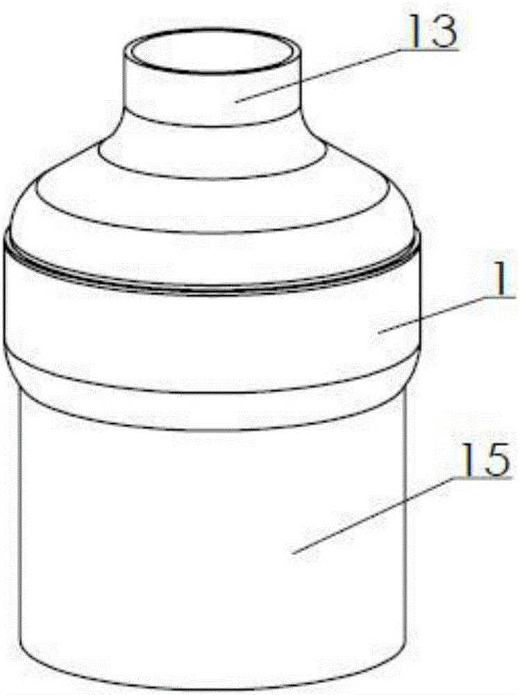
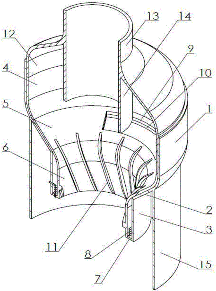
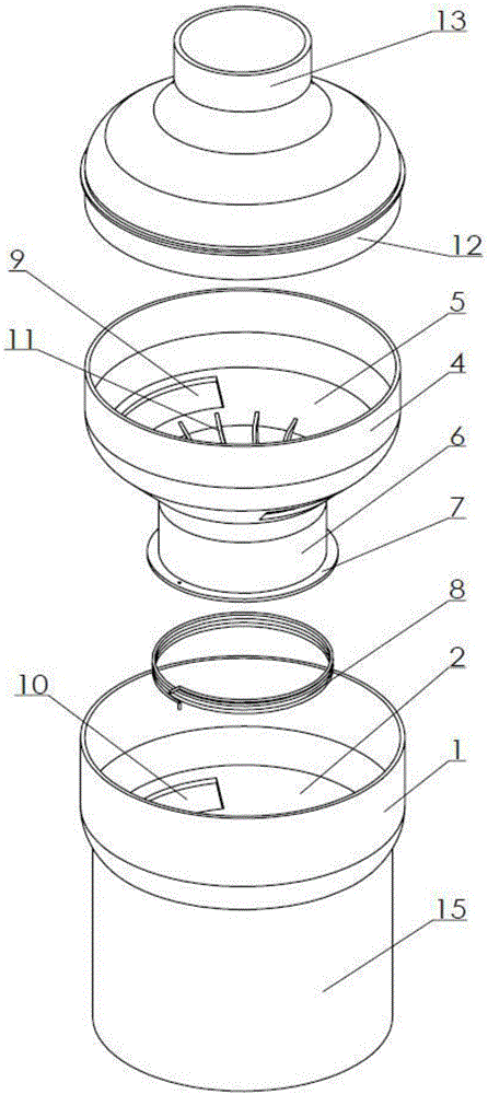
[0011] Examples of the present invention figure 1 , 2 As shown, this constant flow valve for automatic adjustment of oil delivery flow includes a valve body, a valve core and a valve cover. Outer cone 2, the lower section connected to the cone is the lower cylinder 3, the valve core is provided with an inner cylinder 4 that is placed in the upper cylinder and fits with the upper cylinder, and the inner cylinder is connected with a clearance fit with the outer cone The lower end of the inner cone is connected with an inner cylinder 6 coaxial with the lower cylinder, an annular gap is kept between the inner wall of the lower cylinder and the outer wall of the inner cylinder, and the lower end of the inner cylinder is connected with a protruding and lower cylinder. The ring-shaped outer edge 7 fits the inner wall of the cylinder, and the valve core can rotate freely. There is a torsion spring 8 in the annular gap. One end of the torsion spring is connected to the ring-shaped out...


PUM


Abstract

The invention discloses a constant flow valve capable of automatically regulating oil fluid delivery flow. The constant flow valve is characterized in that a middle section connected with an upper cylinder is an outer cone cylinder with diameter gradually shrinking downwards; a lower section connected with the cone cylinder is a lower cylinder; a valve core is provided with an inner cylinder, the inner cylinder is arranged in the upper cylinder, is in clearance fit with the upper cylinder and is connected with an inner cone cylinder which is in clearance fit with the outer cone cylinder, and an inner cylinder coaxial with the lower cylinder is connected to the lower end of the inner cone cylinder; an annular gap is formed between the inner wall of the lower cylinder and the outer wall of the inner cylinder, an annular outer edge which protrudes outwards to be in clearance fit with the lower cylinder is connected to the lower end of the inner cylinder, and a torsion spring is arranged in the annular gap; and inner cone cylinder runners are circumferentially distributed on the inner cone cylinder, the circumferential intervals of the inner cone cylinder runners are larger than the circumferential lengths of the inner cone cylinder runners, outer cone cylinder runners opposite to the inner cone cylinder runners are arranged on the outer cone cylinder, and spirally rising spiral sheets are arranged on the inner wall of the inner cylinder. According to the constant flow valve, the variation amplitude of the flow can be reduced when the pressure is changed, and the flow tending to constant flow is provided.

Description

technical field [0001] The invention relates to a valve for adjusting flow in oil delivery, in particular to a constant flow valve for automatic adjustment of oil delivery flow. Background technique [0002] In oil field production, valves, as flow control components, are an essential part of pipeline transportation. In order to obtain constant flow, most existing valves are realized by manually controlling the opening of the valve. After adjustment, if the pressure fluctuates , the flow rate will also change accordingly, of course, it can also be controlled automatically by electric motor, but the cost is high, and it cannot be widely used, which still needs to be solved by technology. Contents of the invention [0003] In order to solve the above problems, the present invention provides a constant flow valve for automatic adjustment of oil delivery flow. [0004] The technical solution adopted in the present invention is: a constant flow valve for automatic adjustment o...

Claims


Application Information

Patent Timeline
IPC IPC(8): F16K17/20
CPCF16K17/20
Inventor 庞进李俊南周飞范顺平隆正峰
Owner CHONGQING UNIVERSITY OF SCIENCE AND TECHNOLOGY
Learn More