Cap mounting structure

一种安装结构、盖子的技术,应用在运输和包装、车辆部件等方向,能够解决损害外观、模具结构复杂、盖子不能滑动等问题

Inactive Publication Date: 2010-11-24
SUZUKI MOTOR CORP
View PDF5 Cites 0 Cited by
  • Summary
  • Abstract
  • Description
  • Claims
  • Application Information

AI Technical Summary

Problems solved by technology

[0006] Unfortunately, in the technology of Patent Document 1, the thin-walled hinge inserted between the inner member and the cover tends to appear on the design surface, which unnecessarily impairs the appearance
In addition, the mold structure is complex
With the technique of Patent Document 2, since the cover is slidably provided on the inner member, the cover cannot slide at a position bent with a small curvature radius, making it difficult to provide the cover at such a position

Method used


Image

  • Cap mounting structure
  • Cap mounting structure
  • Cap mounting structure

Examples


Embodiment Construction

[0039] Embodiments of the present invention will be described below in conjunction with the accompanying drawings.

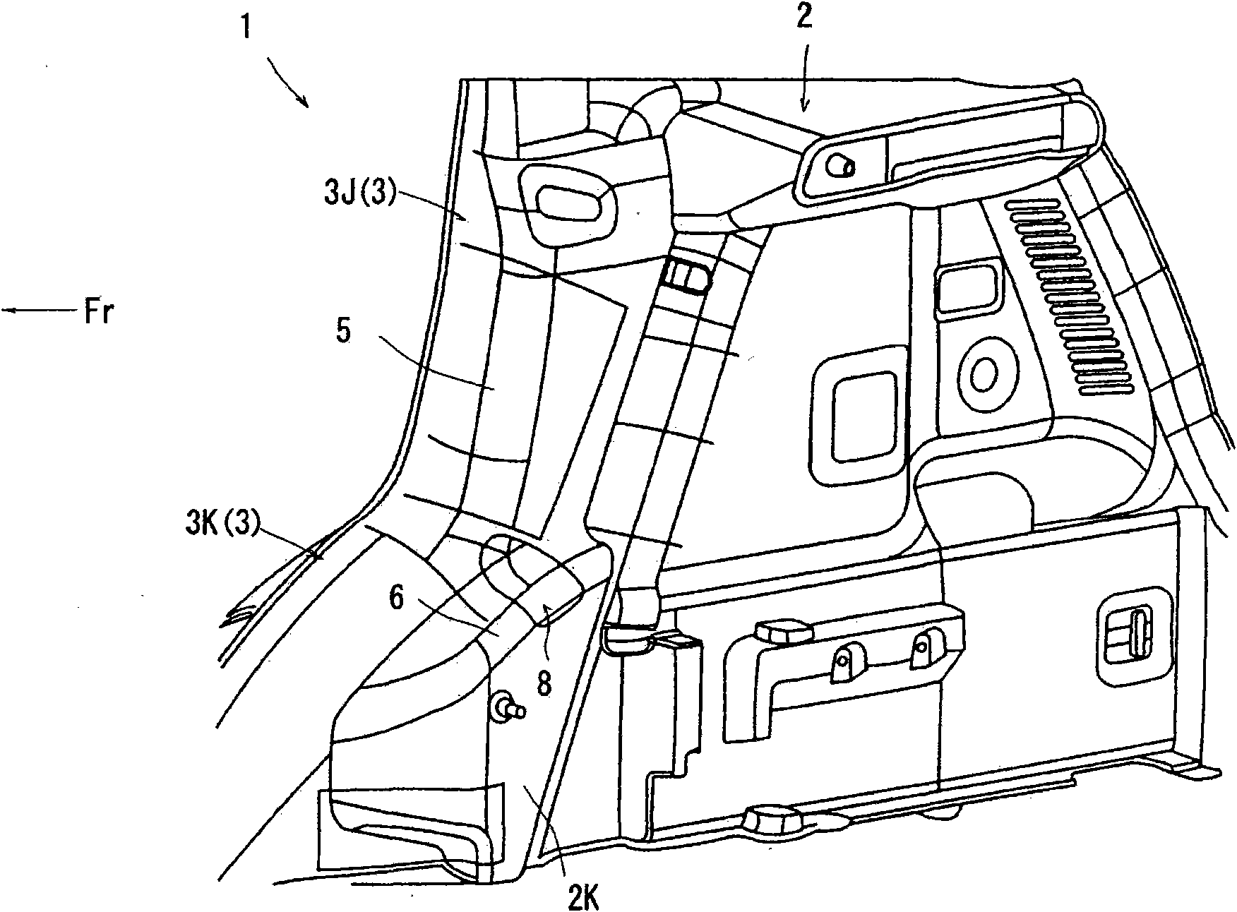
[0040] figure 1 A trunk trim 1 (corresponding to an interior component) of a motor vehicle is shown. The rear trunk trim 1 includes a trapezoidal side wall portion 2 and a front wall portion 3 extending from the front end portion of the side wall portion 2 to the outside in the vehicle width direction, the rear trunk trim 1 covering the cargo box (the rear trunk) behind the rear seat. ). The front wall portion 3 is arranged such that a lower half 3K thereof is formed in a quarter-arc shape convex forward and upward, and an upper half 3J extends obliquely rearward and upward from an upper end portion of the lower half 3K. Front end portions of the lower half 3K of the front wall portion 3 and the lower half 2K of the side wall portion 2 cover the wheel housing.

[0041] As shown in FIG. 5( a ), in the upper half 3J of the front wall portion 3 , a large first o...


PUM


Abstract

A cap mounting structure has an engagement hole formed in a peripheral edge part of an opening in an interior member; a protruding part is formed on a cap; an engagement part engaging with the engagement hole is formed by expanding an intermediate portion in the protrusion direction of the protruding part; the length in the expansion direction of the engagement part is set so as to be longer than the length of the engagement hole; the engagement part is inserted through the engagement hole while at least one of the engagement hole and the engagement part is elastically deformed, and the engagement part is engaged with the engagement hole by the elastic restoration of the elastically deformed part(s), whereby the cap is made in a temporarily held state in which the cap is held by the interior member; and from the temporarily held state, the cap is oscillated so as to be opened and closed.

Description

technical field [0001] The present invention relates to a cover mounting structure for mounting a cover to an opening formed in an internal member. Background technique [0002] The internal member is sometimes formed with an opening for work, including the work of tightening a bolt, and the opening is closed with a cover after the work is completed. [0003] Generally, as the lid mounting structure, there have been adopted, as disclosed in Patent Document 1, a structure in which the lid is swingably provided on the inner member through a thin-walled hinge, and a structure in which the lid is slidable as disclosed in Patent Document 2. The structure set on the internal components. [0004] Patent Document 1: Japanese Patent No. 3364106 [0005] Patent Document 2: JP2002-127802A [0006] Unfortunately, in the technique of Patent Document 1, a thin-walled hinge interposed between the inner member and the cover tends to appear on the design surface, which unnecessarily impai...

Claims


Application Information

Patent Timeline
Patent Type & Authority Applications(China)
IPC IPC(8): B60R13/00
CPCB60R13/0275B60R13/0206B60R2013/0287B60R2013/0281B60R2013/0293
Inventor 河野和典
Owner SUZUKI MOTOR CORP
Why Eureka
Try Eureka