
Acceleration sensor calibration method and device

A technology of acceleration sensor and calibration method, which is applied in the testing/calibration of speed/acceleration/shock measurement equipment, speed/acceleration/shock measurement, measurement device, etc. and other problems to achieve the effect of improving accuracy and convenience

Active Publication Date: 2016-12-14
LAUNCH TECH CO LTD
View PDF5 Cites 7 Cited by
  • Summary
  • Abstract
  • Description
  • Claims
  • Application Information

AI Technical Summary

Problems solved by technology

[0003] The data coordinates output by the acceleration sensor need to undergo a series of space transformations to be converted to the vehicle coordinate system, usually in the following ways: (1) Use the direct coordinate system space conversion method: convert the data of the acceleration sensor to the vehicle coordinate system, according to the transformation Backward centripetal acceleration (also called lateral acceleration, that is, the vertical direction of the vehicle’s forward direction) is used to detect sharp turns. The acceleration sensor in this method has inherent defects, that is, the inaccurate instantaneous acceleration value causes the calculated error to be too large. The reliability of sensor calibration is not high
(2) When the vehicle leaves the factory, the acceleration sensor chip and the vehicle coordinate system are kept coincident; however, this method is only applicable to the pre-installation market. Due to the different installation posture of the OBD in the after-installation market, the direction of the acceleration sensor's own coordinate system cannot be directly given. Therefore, this method cannot be used for aftermarket applications, that is, this method cannot be calibrated for acceleration sensors installed in any attitude

Method used


Image

  • Acceleration sensor calibration method and device
  • Acceleration sensor calibration method and device
  • Acceleration sensor calibration method and device

Examples


Embodiment Construction

[0040] It should be understood that the specific embodiments described here are only used to explain the present invention, not to limit the present invention.

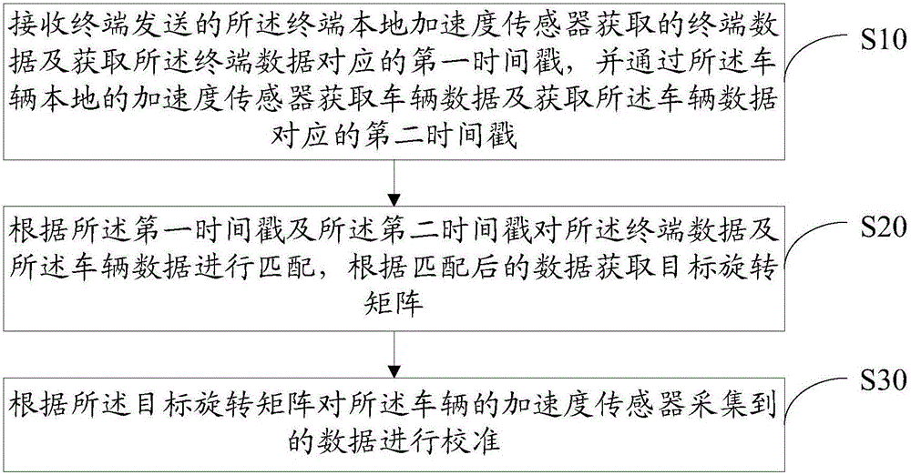
[0041] Such as figure 1 As shown, a first embodiment of an acceleration sensor calibration method of the present invention is shown. The acceleration sensor calibration method of this embodiment includes:

[0042] Step S10, receiving the terminal data acquired by the terminal local acceleration sensor and the first timestamp corresponding to the terminal data sent by the terminal, and acquiring the vehicle data and the corresponding time stamp of the vehicle data through the vehicle local acceleration sensor second timestamp;

[0043] In this embodiment, the acceleration sensor calibration method is applied to the vehicle to calibrate the acceleration sensor included in the OBD, and the OBD includes bluetooth, wifi, and acceleration sensors.

[0044] The acceleration sensor of the vehicle is a three-dimensional acc...


PUM


Abstract

The invention discloses an acceleration sensor calibration method comprising the steps that terminal data acquired by a terminal local acceleration sensor and transmitted by a terminal are received and a first timestamp corresponding to the terminal data is acquired, and vehicle data are acquired through a vehicle local acceleration sensor and a second timestamp corresponding to the vehicle data are acquired; the terminal data and the vehicle data are matched according to the first timestamp and the second timestamp, and a target rotation matrix is acquired according to the matched data; and the data acquired by the vehicle acceleration sensor are calibrated according to the target rotation matrix. The invention also discloses an acceleration sensor calibration device. Accuracy and convenience of acceleration sensor calibration can be enhanced.

Description

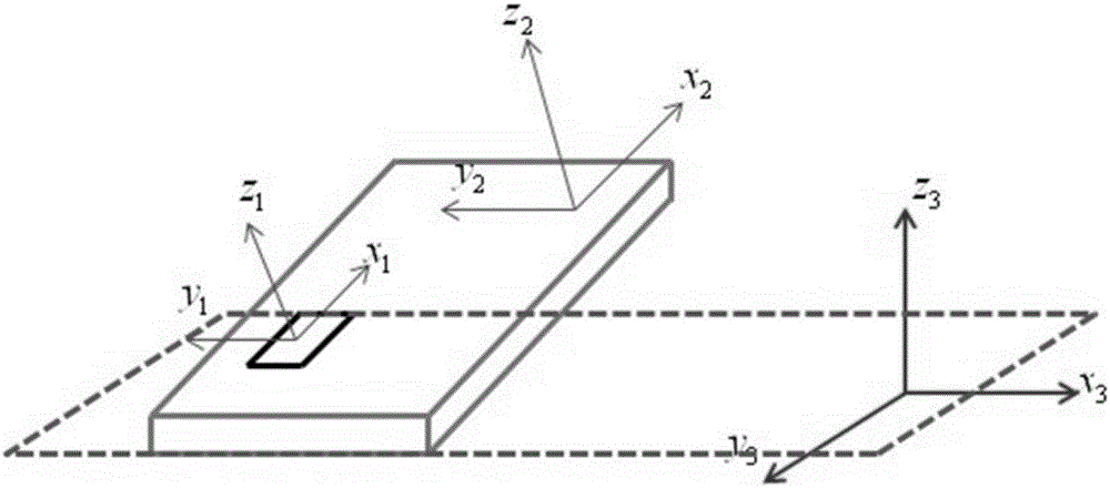
technical field [0001] The invention relates to the technical field of vehicle data acquisition, in particular to an acceleration sensor calibration method and device. Background technique [0002] At present, the On Board Diagnostics (OBD) of the vehicle includes an acceleration sensor. The acceleration sensor of the vehicle is a three-dimensional acceleration detection chip designed according to the inertial pressure model. Generally, the acceleration sensor is used to determine the installation direction of the acceleration sensor chip. , that is, the x-y direction of the plane where the chip is located. In the vehicle, it is generally ensured that the coordinate system x-y-z of the acceleration sensor coincides with the coordinate system x'-y'-z' of the vehicle, and then the data collected by the acceleration sensor is corrected. [0003] The data coordinates output by the acceleration sensor need to undergo a series of space transformations to be converted to the vehic...

Claims


Application Information

Patent Timeline
IPC IPC(8): G01P21/00
CPCG01P21/00
Inventor 刘均李磊
Owner LAUNCH TECH CO LTD
Learn More