
A Method of Image Compression Intra-frame Coding Prediction and Its Hardware Implementation

A technology of intra-frame coding and prediction method, which is applied in the field of image processing, can solve the problems of reducing computation, image quality degradation, not getting rid of loops and comparisons, etc., and achieves the effects of high design flexibility, high processing speed, and short development cycle

Inactive Publication Date: 2019-05-03
赵羽剑
View PDF4 Cites 0 Cited by
  • Summary
  • Abstract
  • Description
  • Claims
  • Application Information

AI Technical Summary

Problems solved by technology

A large number of studies have been devoted to reducing the complexity of intra-frame 4x4 prediction calculations and accelerating intra-frame 4x4 prediction. The most used strategy is to optimize the optimal algorithm for 4x4 prediction modes, such as: selecting the most likely prediction mode according to image content or using some The SAD value of the sampling point is used to replace all the SAD values ​​to reduce the computational complexity, and to sacrifice part of the encoding complexity in exchange for an increase in encoding speed; directly use the correlation of adjacent blocks to determine the most likely prediction mode or calculate the block to be encoded To determine the most probable prediction mode, but it does not get rid of the traversal loop and comparison; by reducing the processing pixel method or the method based on downsampling to reduce the complexity of the operation, the image is sacrificed to a certain extent the quality of
It can be seen that most of these optimization strategies are aimed at software implementation, and do not take into account the parallelism of data during hardware processing, and some of the mode optimization algorithms increase the complexity of mode selection, but do not get a suitable prediction mode. , or the image quality degrades after compression

Method used


Image

  • A Method of Image Compression Intra-frame Coding Prediction and Its Hardware Implementation
  • A Method of Image Compression Intra-frame Coding Prediction and Its Hardware Implementation
  • A Method of Image Compression Intra-frame Coding Prediction and Its Hardware Implementation

Examples


Embodiment Construction

[0023] The following will clearly and completely describe the technical solutions in the embodiments of the present invention with reference to the accompanying drawings in the embodiments of the present invention. Obviously, the described embodiments are only some, not all, embodiments of the present invention. Based on the embodiments of the present invention, all other embodiments obtained by persons of ordinary skill in the art without making creative efforts belong to the protection scope of the present invention.

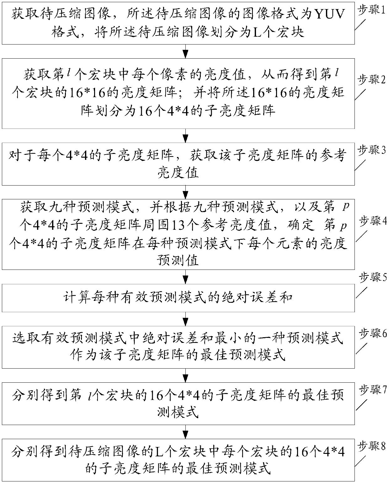
[0024] An embodiment of the present invention provides an image compression intra-frame coding prediction method, referring to figure 1 , the method includes the steps of:

[0025] Step 1, obtain the image to be compressed, the image format of the image to be compressed is YUV format, divide the image to be compressed into L macroblocks, each macroblock contains 16×16 pixels, and L is a natural number greater than 1 .

[0026] Exemplarily, in the embodiment ...


PUM


Abstract

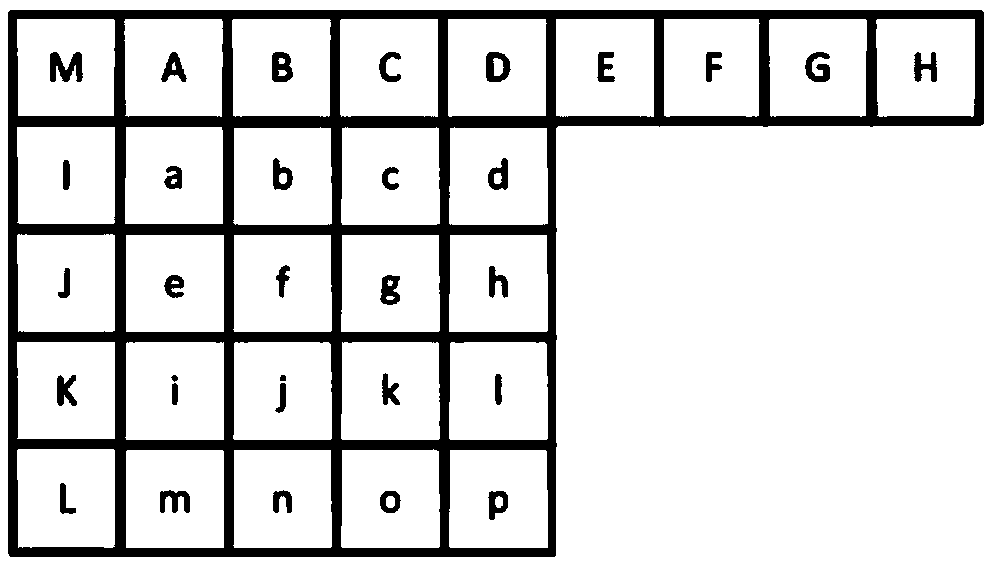
The invention belongs to the technical field of image processing, and discloses an image compression intra-frame coding prediction method and hardware implementation thereof. The image compression intra-frame coding prediction method comprises the following steps: acquiring an image to be compressed, and partitioning the image into L macroblocks; acquiring a brightness value of each pixel in an lth macroblock, and partitioning a brightness matrix of the lth macroblock into 16 4x4 brightness sub-matrixes; acquiring brightness values of 13 elements surrounding a pth brightness sub-matrix; acquiring 9 prediction modes, and calculating a sum of absolute difference of each valid prediction mode; selecting a prediction mode with a minimum sum of absolute difference from the valid prediction modes to serve as an optimal prediction mode of the brightness sub-matrix; adding 1 to a value of p to obtain optimal prediction modes of the 16 4x4 brightness sub-matrixes of the lth macroblock respectively; and adding 1 to a value of l to obtain optimal prediction modes of the 16 4x4 brightness sub-matrixes of each macroblock in the L macroblocks of the image to be compressed respectively.

Description

technical field [0001] The present invention relates to the field of image processing technology, in particular to an image compression intra-frame coding prediction method and its hardware implementation, which can be applied to the fields of video monitoring, video conferencing, biomedicine, information security, remote sensing and telemetry, aerospace, video multimedia, etc. . Background technique [0002] At present, H.264 is already a very mature video compression coding standard, and its application scope is gradually expanding. There are already many H.264 video compression coding solutions on the market. Software coding can fully realize the entire H.264 coding system, but the coding process involves a lot of mathematical operations, so the running speed of software implementation is very slow, and it is easy to cause bus congestion. For real-time systems with high requirements, software encoders are limited Hardware, it is difficult to meet the requirements of real...

Claims


Application Information

Patent Timeline
Patent Type & Authority Patents(China)
IPC IPC(8): H04N19/159H04N19/176H04N19/11H04N19/463
CPCH04N19/11H04N19/159H04N19/176H04N19/463
Inventor 赵羽剑韦炜
Owner 赵羽剑
Learn More