Securing the shaft in a cone crusher

A cone crusher and cone technology, applied in grain processing and other directions, can solve the problems of difficult to remove the main shaft, complicated cone support, etc., to avoid the difficulty of positioning the oil pipe, avoid the complicated removal and installation, and the large clamping force. Effect

Active Publication Date: 2016-12-14
F L SMIDTH & CO AS
View PDF12 Cites 0 Cited by
  • Summary
  • Abstract
  • Description
  • Claims
  • Application Information

AI Technical Summary

Problems solved by technology

At least for the precision required (in particular the oil passages running in the main shaft rely on precise axial positioning) it is at least complicated, if not impossible, to manufacture a conical seat of this length
In addition, it is difficult to remove the spindle for servicing, which is fixedly pressed into its conical bearings by manipulation

Method used


Image

  • Securing the shaft in a cone crusher
  • Securing the shaft in a cone crusher

Examples


Embodiment Construction

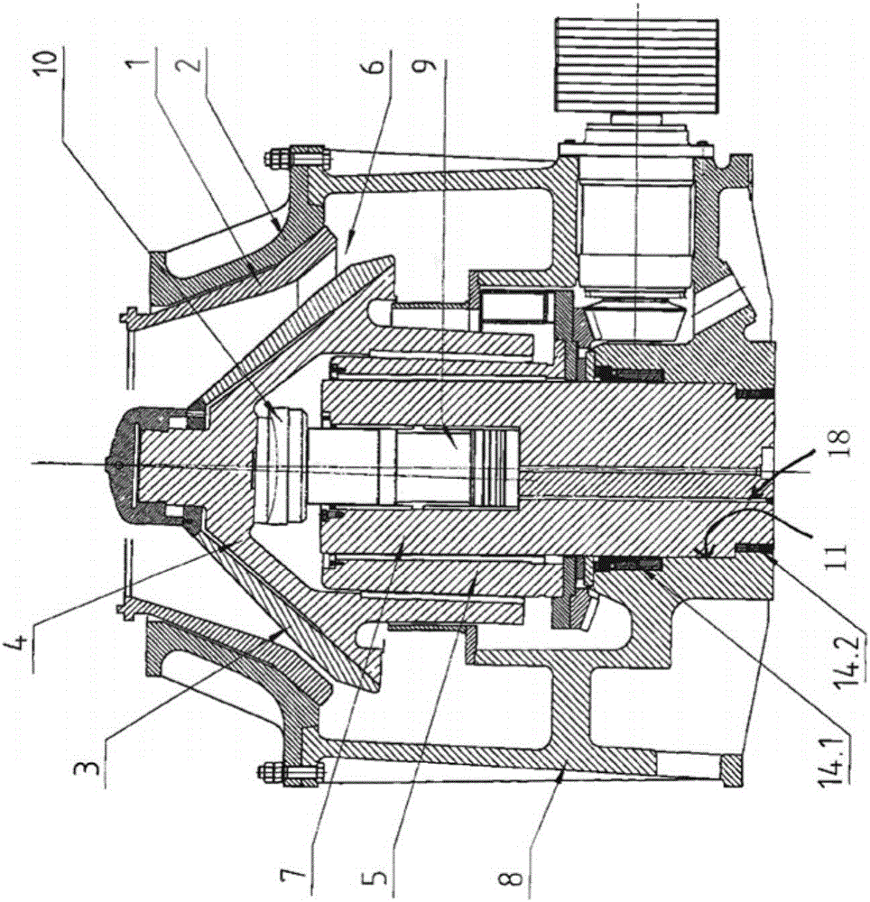
[0022] first figure 1 A section through the head of a cone crusher according to the invention is shown. The material for crushing supplied to the cone crusher is crushed between the stationary crushing ring 1 of the upper part 2 of the housing and the crushing cone 3 sitting on the conical seat of the cone carriage 4 . The cone carrier 4 is set in an oscillating movement via the driven eccentric bushing 5, with the result that the crushing gap 6 between the crushing ring 1 and the crushing cone 3 changes in a continuously rotating manner. In the crushing gap 6 the material for crushing is comminuted by extrusion and impact until said material is able to leave the cone crusher through the crushing gap 6 .

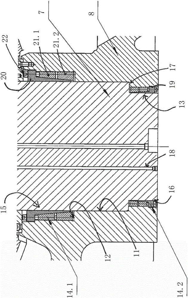
[0023] The driven eccentric bushing 5 rotates and is guided radially about a main shaft 7 which is fixedly clamped in the housing lower part 8 . For the axial support of the cone carrier 4 , a spherical thrust bearing 10 is used which is arranged on the head of the cylindr...


PUM


Abstract

Disclosed is a cone crusher comprising a crusher cone that is retained on a driven eccentric bush that rotates about a journal (7) while being radially guided. The journal (7) is securely clamped in a journal holder (11) located in the lower housing part (8) and has a cylindrical upper supporting section (15) which is clamped, by means of an upper mechanical clamping device (14.1), in a bore forming the journal holder (11).

Description

technical field [0001] The invention relates to a cone crusher with a crushing cone supported on a driven eccentric bushing, wherein the eccentric bushing rotates in a radial direction around a crusher shaft designed as a main shaft and fixedly clamped in In the shaft seat provided in the lower part of the housing. Background technique [0002] Not only cone crushers of this type but also gyratory crushers have long been known in the prior art. Depending on their purpose of use, ie crushing large quantities of rock mass, these crushers are exposed to harsh environments, are subjected to high loads and correspondingly high wear. In order to be able to ensure reliable operation, the wearing parts, including in particular the crushing cone supported on the cone carrier and the abutment of the cone carrier, must be replaced from time to time. If these operations can be performed quickly in situ, it is beneficial for the service life. However, due to the very uncomfortable ext...

Claims


Application Information

Patent Timeline
Patent Type & Authority Applications(China)
IPC IPC(8): B02C2/04
CPCB02C2/04B02C2/00B02C2/047B02C2/06
Inventor S·费希尔H-J·梅克
Owner F L SMIDTH & CO AS
Why Eureka
Try Eureka