
Indicating devices for power tools

A technology for indicating devices and power tools, which can be used in portable mobile devices, manufacturing tools, lighting devices, etc., and can solve the problems of being unable to respond to light instructions and being invisible

Active Publication Date: 2019-11-08
ATLAS COPCO INDAL TECHN AB
View PDF7 Cites 0 Cited by
  • Summary
  • Abstract
  • Description
  • Claims
  • Application Information

AI Technical Summary

Problems solved by technology

That is, during operation, the operator may need to keep his eyes fixed on the workpiece, so that he may not be able to respond to the emitted light indications
This may also be due to the location of the indicator on the tool which may not be visible to the operator in a particular work position

Method used


Image

  • Indicating devices for power tools
  • Indicating devices for power tools
  • Indicating devices for power tools

Examples


Embodiment Construction

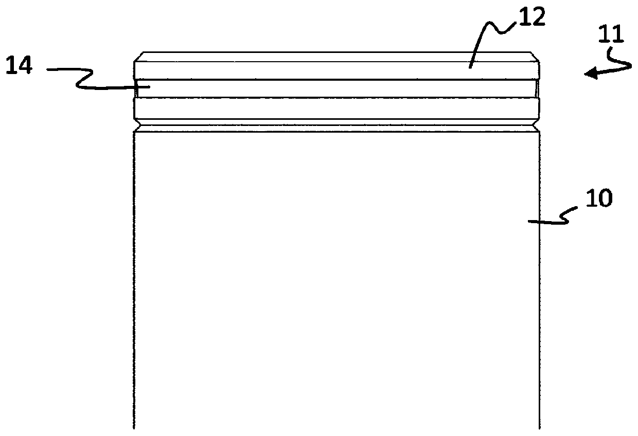
[0022] figure 1 A side view of one end of a power tool 10 having an indicating device 11 according to a particular embodiment of the invention is shown. as available from figure 1 As seen in the view of FIG. 1 , the pointing device 11 includes a cover 12 and a light transmission lens 14 .

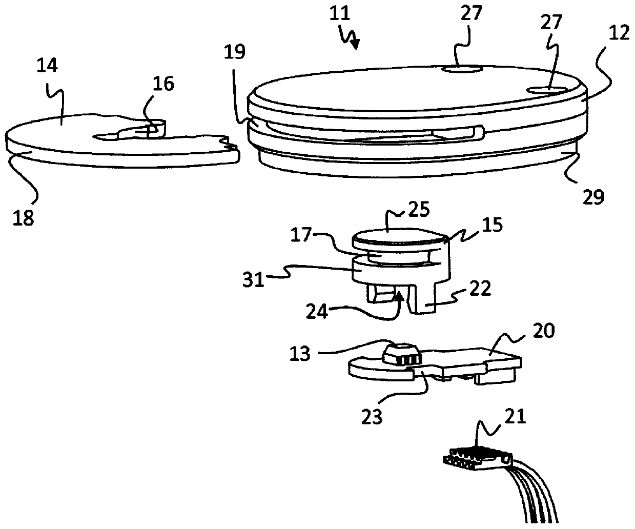
[0023] exist figure 2 In , the indicating device 11 is shown in an exploded view so that the internal components of the indicating device 11 can be seen.

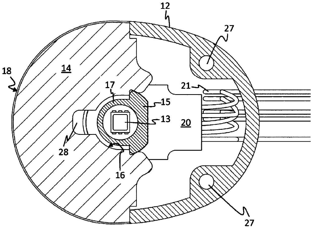
[0024] The indicating device 11 comprises a light source 13, for example an LED. The reflector 15 is configured to accommodate the light source 13 . In the embodiment shown, the light source 13 is arranged on a circuit board 20 which can be connected via a connection 21 to a voltage source inside the tool housing. The circuit board 20 is adapted to be secured to the reflector via a snap connection comprising a snap connector 22 on the reflector 15 configured to surround a The waist 23 is engaged.

[0025] The reflector 15 has an ...


PUM


Abstract

The invention relates to an indicating device (11) for a power tool (10), comprising a cover (12), an electric light source (13) and at least one light-transmitting lens (14). The indicating device (11) comprises a reflector (15) in which said electric light source (13) is at least partially contained. The lens (14) has a planar shape extending from the inner surface (16) facing the light-emitting part (17) of the emitter (15) to the outer surface (18) and adapted to pass through the At least one slot-shaped opening (19) extends wherein the lens (14) is configured to emit light in a plurality of directions along the cover (12) separated by an angle of at least 90 degrees, thereby providing light visible from different angles of the pointing device Signal.

Description

technical field [0001] The invention relates to an indicating device for a power tool. In particular, the invention relates to an indicating device having improved visibility. Background technique [0002] Power tools (for example, nutrunners or screwdrivers) are becoming increasingly complex. Today's conventional industrial power tools are provided with sensors (eg angle encoders and / or torque meters) which enable control of the quality of the operating work performed (eg tightening a joint). Many power tools are therefore provided with some kind of indicating device configured to signal to the operator that the operation performed is OK or NOK. Typically, a successful operation job (OK) can be indicated with a green light and an unsuccessful operation job (NOK) can be indicated with a red light. [0003] A problem with conventional pointing devices is the location of the pointing device. That is, during operation, the operator may need to keep his eyes fixed on the wor...

Claims


Application Information

Patent Timeline
Patent Type & Authority Patents(China)
IPC IPC(8): B25F5/02
CPCB25F5/021B25F5/02F21V5/048F21V7/10F21V17/104F21V33/0084
Inventor H·J·A·桑德尔其他发明人请求不公开姓名
Owner ATLAS COPCO INDAL TECHN AB
Learn More