Orthodontic pliers

An orthodontic and forceps arm technology, applied in the field of orthodontic forceps, can solve the problems of increased purchase cost, waste of resources, discarding of orthodontic forceps, etc., and achieve the effects of saving resources, improving equipment utilization, and convenient replacement.

Inactive Publication Date: 2016-12-21
SHENZHEN INST OF ADVANCED TECH CHINESE ACAD OF SCI
View PDF5 Cites 3 Cited by
  • Summary
  • Abstract
  • Description
  • Claims
  • Application Information

AI Technical Summary

Problems solved by technology

In order to improve work efficiency, orthodontists often need to be equipped with a variety of orthodontic pliers with different pliers heads. Although this can bring efficiency and convenience to the work, it increases the cost of purchase, and also causes inconvenience to equipment maintenance and carrying, which is harmful to society. resources are also a waste
In addition, the existing orthodontic pliers on the market are basically made of medical stainless steel, and the manufacturing process requirements are high, resulting in expensive orthodontic pliers
Most of the orthodontic pliers with different functions only have different shapes of the pliers head, but the shape of the pliers body is consistent. The damage of orthodontic pliers often occurs in the pliers head part and is difficult to repair. In most cases, the pliers body is still intact, but Orthodontic forceps have to be discarded due to damage to the forceps head, resulting in a waste of resources

Method used


Image

  • Orthodontic pliers
  • Orthodontic pliers
  • Orthodontic pliers

Examples


Embodiment 1

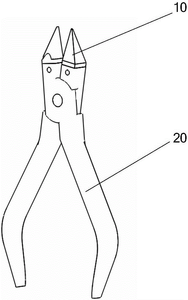
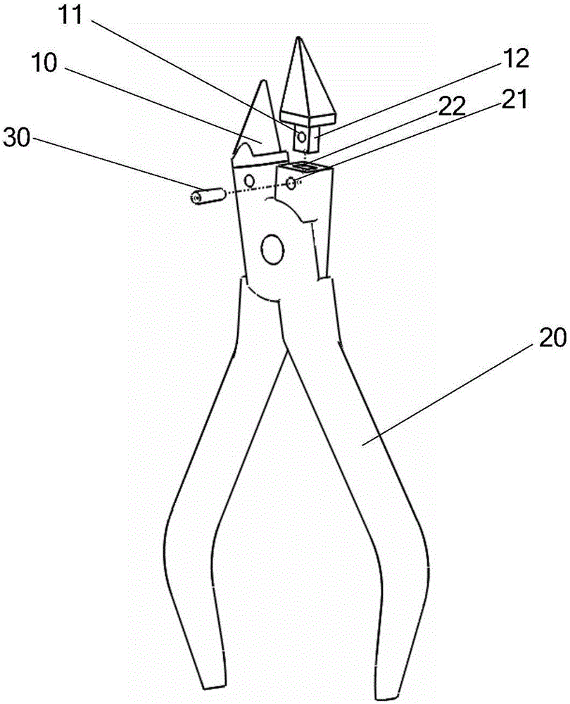
[0019] Such as figure 1 , figure 2 As shown, the orthodontic pliers of the present application, an embodiment thereof, includes a pliers head 10, a pliers arm 20 and a fastener 30, the pliers head 10 is provided with a first mounting hole 11, and the pliers arm 20 is provided with a second mounting hole 21. Fasteners 30 are passed through the first installation hole 11 and the second installation hole 21, the fasteners 30 are interference fit with the first installation hole 11 and the second installation hole 21 respectively, and the pliers head 10 passes through the fasteners 30 is detachably installed on the pliers arm 20. The first installation hole 11 of the present application may include a tapered hole, and the second installation hole 21 may also include a tapered hole. The fastener 30 may include a pin, specifically a tapered pin.

[0020] In one embodiment, the pliers head 10 is provided with a boss 12, the first installation hole 11 is arranged on the boss 12, t...

Embodiment 2

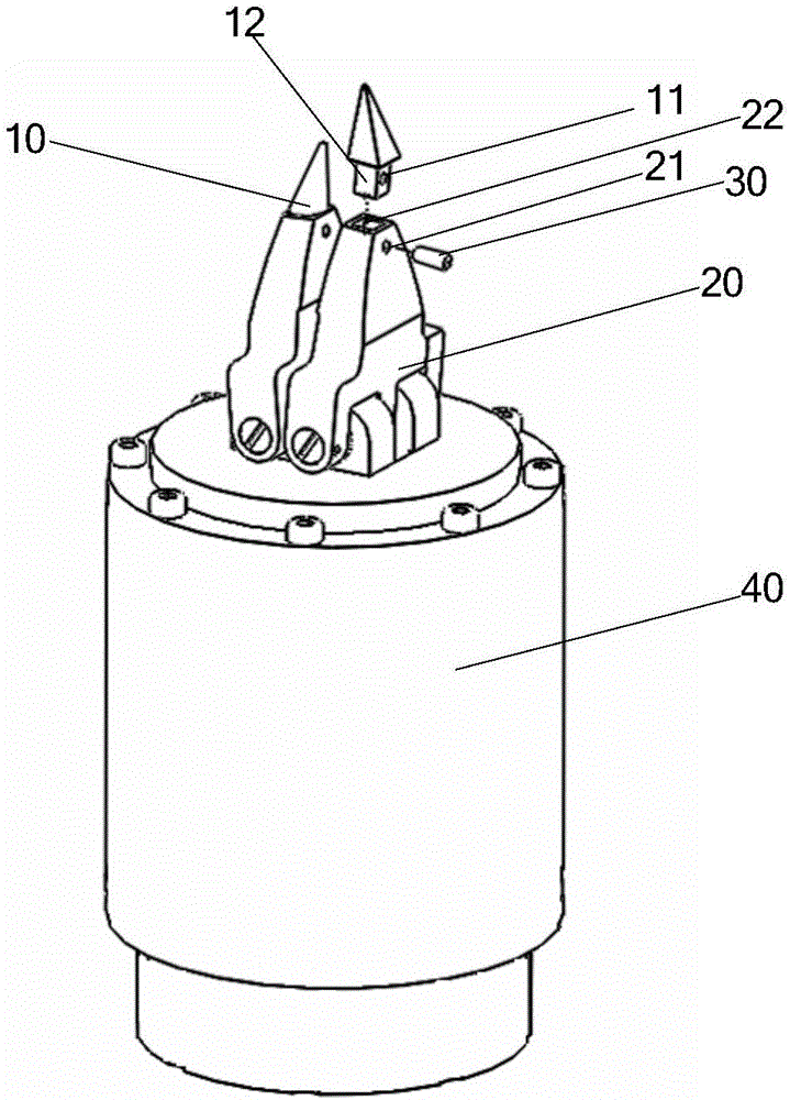
[0025] Such as image 3 As shown, this embodiment is a robotic orthodontic forceps. The difference between this embodiment and Embodiment 1 is that it also includes a mechanical arm 40 on which the forceps arm 20 is arranged.


PUM


Abstract

The application discloses a pair of orthodontic pliers. The pair of orthodontic pliers comprises a pliers head and pliers arms and further comprises a fastener, wherein the pliers head is provided with a first mounting hole; each of the pliers arms is provided with a second mounting hole; the fastener is arranged in the first mounting hole and the second mounting hole in a penetrating manner; the fastener is in interference fit with the first mounting hole and the second mounting hole, respectively; the pliers head is detachably mounted on the pliers arms through the fastener. In the specific embodiment of the application, since the orthodontic pliers comprise the pliers head, the pliers arms and the fastener, the pliers head is provided with the first mounting hole; each pliers arm is provided with the second mounting hole; the fastener is arranged in the first mounting hole and the second mounting hole in a penetrating manner; the pliers head is detachably mounted on the pliers arms through the fastener; fixed connection between the pliers head and the pliers body can be ensured through a simple structure in interference fit through the fastener, while convenient replacement of different pliers heads is realized to achieve multiple purposes, so that the utilization rate of equipment is improved and resources are saved.

Description

technical field [0001] The present application relates to medical instruments, in particular to an orthodontic forceps. Background technique [0002] Orthodontic forceps are orthodontic instruments used by orthodontists to assist in the preparation of archwire appliances. Orthodontists need to choose different orthodontic forceps according to the needs during the preparation process, and various orthodontic forceps with different forceps head shapes have appeared on the market, such as: filament curved forceps, filament bird's beak forceps, Tweed curved trapezoidal forceps, Kim pliers, torque forming pliers, etc. In order to improve work efficiency, orthodontists often need to be equipped with a variety of orthodontic pliers with different pliers heads. Although this can bring efficiency and convenience to the work, it increases the cost of purchase, and also causes inconvenience to equipment maintenance and carrying, which is harmful to society. Resources are also a waste...

Claims


Application Information

Patent Timeline
Patent Type & Authority Applications(China)
IPC IPC(8): A61C7/04
CPCA61C7/04
Inventor 夏泽洋翁少葵熊璟
Owner SHENZHEN INST OF ADVANCED TECH CHINESE ACAD OF SCI
Why Eureka
Try Eureka