Method and device for detecting connection state between battery and vehicle body, controller and medium

A connection status and detection method technology, which is applied in electrical connection testing, battery/fuel cell control devices, electrical devices, etc., can solve problems such as long charging time and inconvenient use, achieve reliable detection results, prevent battery drop, The effect of safe driving

Inactive Publication Date: 2018-08-14
NIO ANHUI HLDG CO LTD
View PDF8 Cites 3 Cited by
  • Summary
  • Abstract
  • Description
  • Claims
  • Application Information

AI Technical Summary

Problems solved by technology

[0002] Long charging time and inconvenient use of electric vehicles are the main factors affecting the large-scale development of electric vehicles. Therefore, electric vehicle battery replacement technology has emerged as the times require

Method used


Image

  • Method and device for detecting connection state between battery and vehicle body, controller and medium
  • Method and device for detecting connection state between battery and vehicle body, controller and medium
  • Method and device for detecting connection state between battery and vehicle body, controller and medium

Examples


Embodiment 1

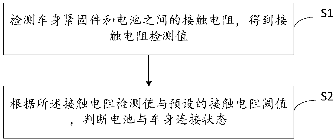
[0082] Step S11 , detecting the contact resistance between each vehicle body fastener and the battery one by one, and obtaining the contact resistance detection value between each vehicle body fastener and the battery.

[0083] Step S11 includes:

[0084] Step S111, connecting a detection circuit between each vehicle body detection point and the corresponding battery detection point to form a detection loop;

[0085] Step S112, obtain the contact resistance value between each vehicle body detection point and the corresponding battery detection point through the detection circuit,

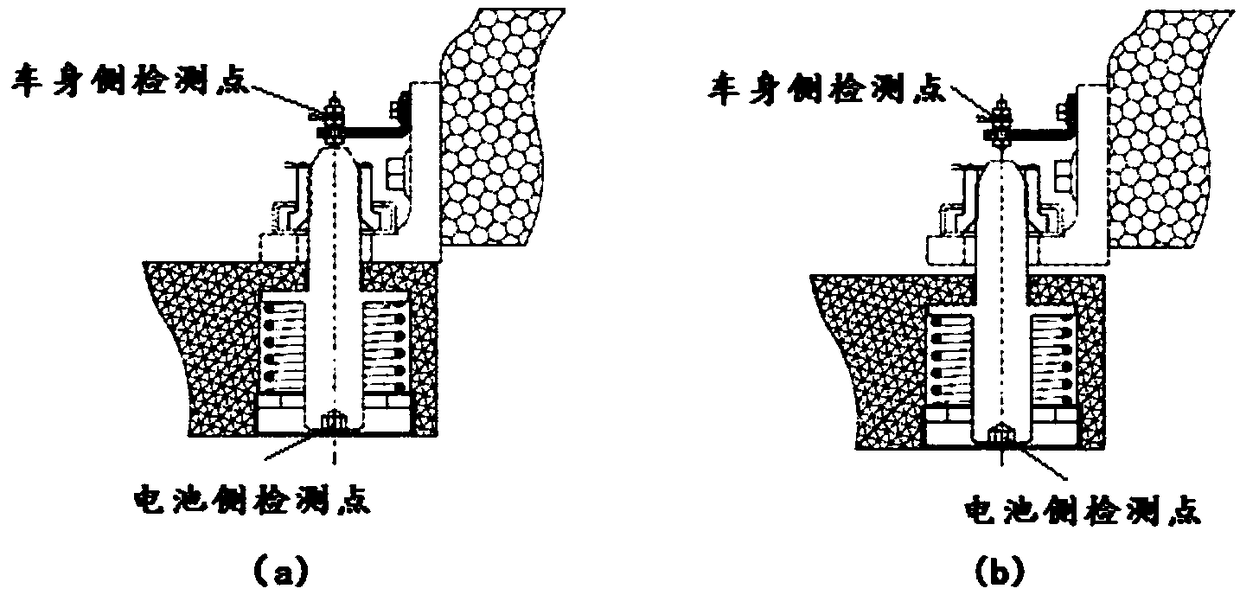
[0086] Wherein, one body detection point is set on each body fastener, all the battery detection points are located on the battery side, and each body detection point corresponds to a battery detection point. Such as image 3 As shown in , respectively show the state of fastening and loosening of the connection, as well as the location of the detection points on the body side and battery side.

...

Embodiment 2

[0091] In the actual detection process, since the method of detecting a single contact resistance described in Embodiment 1 is directly used, a detection circuit needs to be established between the vehicle body and the battery, and the detection process is relatively difficult, so the following process can be used for detection:

[0092] Step S12, assuming that there are M body fasteners in total on the electric vehicle, wherein M is an integer greater than or equal to 2,

[0093] Divide M body fasteners into N groups, where N is an integer greater than or equal to 1, each group includes P body fasteners, where 2≤P≤M, and N groups of fasteners include each body fasteners;

[0094] It should be noted that there are many ways of grouping, which can be set according to specific testing requirements, for example, testing can be done in pairs, that is, two-two testing, or a group of three, a group of four, and so on. The number of body fasteners included in each group can be the s...

Embodiment 3

[0124] The detection circuit 1 is also used to connect each vehicle body detection point and the corresponding battery detection point, detect the contact resistance between each body fastener and the battery one by one, and obtain the contact resistance detection value between each body fastener and the battery .

[0125] Wherein, the vehicle body detection point is located on the body fastener on the side of the vehicle body, the battery detection point is located on the battery side, and each vehicle body detection point corresponds to a battery detection point. Such as image 3 As shown in , respectively show the state of fastening and loosening of the connection, as well as the location of the detection points on the body side and battery side.

[0126] The judgment module 2 is used for:

[0127] Comparing the contact resistance detection value between each body fastener and the battery with the contact resistance threshold value between the corresponding body fastener ...


PUM


Abstract

The invention relates to a method and device for detecting a connection state between a battery and a vehicle body, a controller and a medium. The method comprises the steps of detecting the contact resistance between one or more vehicle body fasteners and the battery to obtain a contact resistance detection value; determining the connection state between the battery and the vehicle body accordingto the contact resistance detection value and the preset contact resistance threshold value. According the method, whether or not the fasteners are tightened in place is determined by detecting the contact resistance between the battery and the vehicle body fasteners to further judge whether or not the battery is firmly installed; the detection process is simple, the detection result is reliable,the reliability and safety of power exchange are ensured, and safe driving of a power exchange vehicle is ensured.

Description

technical field [0001] The invention relates to the technical field of electric vehicles, in particular to a detection method and device, a controller and a medium for detecting the connection state of a battery and a vehicle body. Background technique [0002] Long charging time and inconvenient use of electric vehicles are the main factors affecting the large-scale development of electric vehicles. Therefore, electric vehicle battery replacement technology has emerged as the times require. Battery swapping is a way to quickly replenish energy for electric vehicles. Specifically, it refers to a way for electric vehicles to remove the power battery of the vehicle through the battery swapping device and immediately replace another set of power batteries. The swap station is a place where the power battery of an electric vehicle is swapped. [0003] The safety and reliability of the vehicle after battery replacement is the basic requirement for battery replacement. Fasteners...

Claims


Application Information

Patent Timeline
Patent Type & Authority Applications(China)
IPC IPC(8): G01R31/02B60L11/18
CPCB60L50/64B60L58/10G01R31/50G01R27/205Y02T10/70B60L3/00B60L2250/10B60L53/80G01R31/69Y02T10/7072
Inventor 郝战铎陈炯马骏
Owner NIO ANHUI HLDG CO LTD
Why Eureka
Try Eureka