
Novel computer dust removing device

A dust removal device and computer technology, applied in the direction of dust removal, cleaning method and utensils, cleaning method using tools, etc., can solve the problem of reducing the heat dissipation effect of heat dissipation through holes, polluting the computer working environment, reducing the performance and safety performance of computer equipment, etc. problems, to achieve the effect of improving dust removal efficiency and dust removal effect, and convenient and quick dust removal operation

Inactive Publication Date: 2016-12-21
成都聚立汇信科技有限公司
View PDF4 Cites 16 Cited by
  • Summary
  • Abstract
  • Description
  • Claims
  • Application Information

AI Technical Summary

Problems solved by technology

During the use of computer equipment, in order to ensure its effective ventilation and heat dissipation, heat dissipation through holes are often provided on the computer equipment, but at the same time, the problem that exists is that with long-term use, the heat dissipation through holes of the computer A large amount of dust will accumulate in the place, which not only greatly reduces the heat dissipation effect of the heat dissipation through hole, but also pollutes the working environment of the computer. However, due to the limitation of structure and design, the existing computer equipment is often not convenient and fast. The dust removal operation is not performed properly, and the dust removal effect is not ideal, which greatly reduces the performance and safety performance of computer equipment.

Method used


Image

  • Novel computer dust removing device

Examples


Embodiment Construction

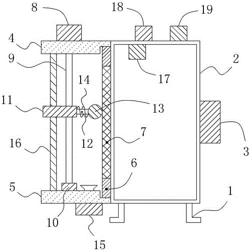
[0013] like figure 1 As shown, a novel computer dust removal device comprises a support 1 and a chassis 2 located on the support 1, an air suction port is provided on the right side wall of the chassis 2, an air extractor 3 is provided at the suction port, and an air extractor 3 is arranged on the side of the chassis 2 The left side wall is uniformly provided with a plurality of ventilation holes, and an upper support plate 4 extending horizontally to the left is connected to the top of the left side wall of the cabinet 2, and an upper support plate 4 extending horizontally to the left is connected to the bottom of the left side wall of the cabinet 2. The lower support plate 5 of the upper support plate 4 is also provided with an upper groove at the bottom right end of the upper support plate 4, and a lower groove is also provided at the top right end of the lower support plate 5; a dust filter frame 6 is also provided on the left side of the chassis 2 to filter dust The upper...


PUM


Abstract

The invention relates to a novel computer dust removing device. The novel computer dust removing device comprises a support and a machine case. An air extraction opening and an air extractor are arranged on the right side wall of the machine case. Ventilation holes are evenly formed in the left side wall of the machine case. An upper supporting plate is connected to the top of the left side wall of the machine case, and a lower supporting plate is connected to the bottom of the left side wall of the machine case. An upper groove is formed in the right end of the bottom of the upper supporting plate, and a lower groove is formed in the right end of the top of the lower supporting plate. A dust filtering frame is arranged on the left of the machine case and internally further provided with a dust filtering net. A motor is further arranged on the upper supporting plate. The bottom end of an output shaft of the motor is connected with a screw. The bottom end of the screw is rotationally connected with the lower supporting plate through a bearing. The screw is further sleeved with a lifting block in threaded fit with the screw. A supporting rod is connected to the right end of the lifting block. The right end of the supporting rod is connected with a brush rod. The brush rod is closely attached to the left side of the dust filtering net. Meanwhile, brush bristles are further evenly distributed on the brush rod. By the adoption of the above structure, the novel computer dust removing device can conveniently and rapidly conduct the dust removing operation, and therefore the dust removing efficiency and the dust removing effect are greatly improved.

Description

technical field [0001] The invention relates to a novel computer dust removal device. Background technique [0002] With the continuous development of computer technology, more and more computer devices are widely used in various occasions of life and work. During the use of computer equipment, in order to ensure its effective ventilation and heat dissipation, heat dissipation through holes are often provided on the computer equipment, but at the same time, the problem that exists is that with long-term use, the heat dissipation through holes of the computer A large amount of dust will accumulate in the place, which not only greatly reduces the heat dissipation effect of the heat dissipation through hole, but also pollutes the working environment of the computer. However, due to the limitation of structure and design, the existing computer equipment is often not convenient and fast. The dust removal operation is not performed properly, and the dust removal effect is not ide...

Claims


Application Information

Patent Timeline
IPC IPC(8): B08B1/00B08B13/00B08B15/04
CPCB08B13/00B08B15/04B08B1/30B08B1/12
Inventor 吕静
Owner 成都聚立汇信科技有限公司
Learn More