
Locking puncher pin

A technology of punches and punches, applied in metal processing equipment, forming tools, manufacturing tools, etc., can solve the problems of difficult installation and disassembly of punches, and achieve the effect of simple structure, easy installation and disassembly, and cost saving

Active Publication Date: 2016-12-21
SUZHOU ZHONGTUO PATENT OPERATION MANAGEMENT CO LTD
View PDF5 Cites 0 Cited by
  • Summary
  • Abstract
  • Description
  • Claims
  • Application Information

AI Technical Summary

Problems solved by technology

[0003] The technical problem mainly solved by the present invention is to provide a locking punch with reasonable design and simple structure, which solves the problem that the punch is not easy to install and disassemble

Method used


Image

  • Locking puncher pin
  • Locking puncher pin
  • Locking puncher pin

Examples


Embodiment Construction

[0013] The preferred embodiments of the present invention will be described in detail below with reference to the accompanying drawings, so that the advantages and features of the present invention can be more easily understood by those skilled in the art, so as to make a clearer and clearer definition of the protection scope of the present invention.

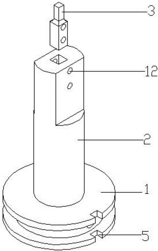
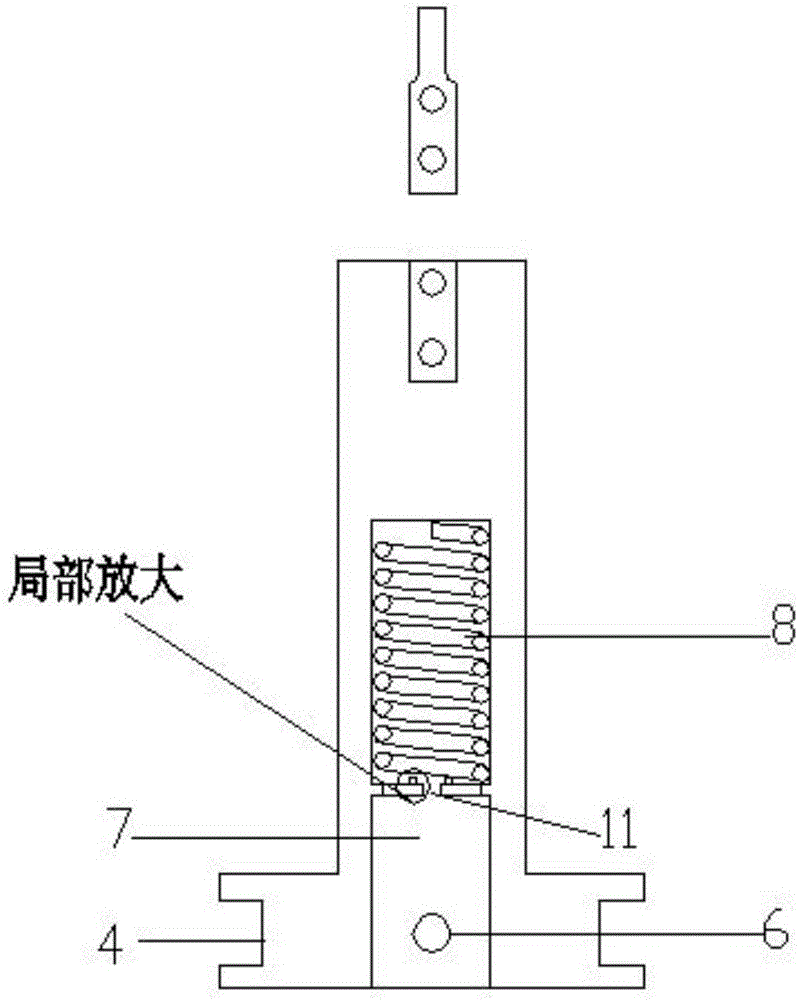
[0014] See attached figure 1 with figure 2 , The embodiment of the present invention includes: a round table 1, a punch 2 and a plug 3; the lower surface of the round table 1 is connected with the upper surface of the punch 2; the upper end of the plug 3 is inserted in the butting groove at the lower end of the punch 2; The circular table 1 is provided with an annular groove 4, and one side of the circular table 1 is also provided with a clamping groove 5; the circular groove 4 in the middle of the clamping groove 5 is provided with a fastening screw hole 6; 1 and the center of the punch 2 are provided with a semi-permeable hole 7...


PUM


Abstract

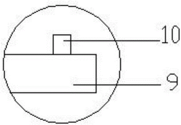
The invention discloses a locking puncher pin. The locking puncher pin comprises a circular truncated cone, a punch rod and an ejector header. The lower surface of the circular truncated cone is connected with the upper surface of the punch rod. The upper end of the ejector header is inserted into a butt joint groove formed in the lower end of the punch rod. An annular groove is formed in the circular truncated cone, and clamping grooves are further formed in one side of the circular truncated cone. A fastening screw hole is formed in the annular groove between the clamping grooves. A semi-through hole is formed in the center of the circular truncated cone and the center of the punch rod. The fastening screw hole communicates with the semi-through hole. An annular buckle is arranged in the middle of the semi-through hole. Two symmetric ends are arranged on the annular buckle, and buckle bodies are arranged on the lower surfaces of the two sides of the annular buckle correspondingly. A spring is arranged under the annular buckle, the lower end of the spring abuts against the bottom surface of the semi-through hole, and the upper end of the spring abuts against the lower surface of the annular buckle. The lower end of the punch rod and the upper end of the ejector header are each provided with two fixing holes, and the fixing holes are matched. The locking puncher pin is simple in structure, reasonable in design, convenient to mount and dismount, sufficient in strength and good in manufacturability; and workers can operate the locking puncher pin easily and conveniently, and the working efficiency is improved.

Description

Technical field [0001] The invention relates to the field of molds, in particular to a locking punch. Background technique [0002] Punches are also called punches, upper molds, male molds, punches, etc., and punches are divided into A-type punches, T-type punches, and special-shaped punches. The punch is a metal part installed on the stamping die, which is used in direct contact with the material to deform and cut the material. However, most of the existing punches have complex structures and are not easy to install and disassemble. The punches are easy to break. When broken, they cannot be replaced, which causes great waste. Moreover, the punches are single, and different sizes of plugs cannot be replaced according to their needs. Therefore, the cost is high. Summary of the invention [0003] The main technical problem solved by the present invention is to provide a locking punch with reasonable design and simple structure, which solves the problem that the punch is not easy t...

Claims


Application Information

Patent Timeline
Patent Type & Authority Applications(China)
IPC IPC(8): B21D37/10B21D37/04
CPCB21D37/04B21D37/10
Inventor 顾林男
Owner SUZHOU ZHONGTUO PATENT OPERATION MANAGEMENT CO LTD
Learn More