Novel roller transport vehicle
A transport vehicle and roller technology, applied in the field of new roller transport vehicles, can solve the problems of inconvenient storage, collision damage, roller rolling, etc.
- Summary
- Abstract
- Description
- Claims
- Application Information
AI Technical Summary
Problems solved by technology
Method used
Image

Examples
Embodiment Construction
[0029] Specific embodiments of the present invention will be described in detail below in conjunction with the accompanying drawings. It should be understood that the specific embodiments described here are only used to illustrate and explain the present invention, and are not intended to limit the present invention.
[0030] In the present invention, in the absence of a contrary description, the orientation words included in the term, such as "inside and outside", only represent the orientation of the term in the normal use state, or the common name understood by those skilled in the art, and should not be viewed as a limitation of this term.
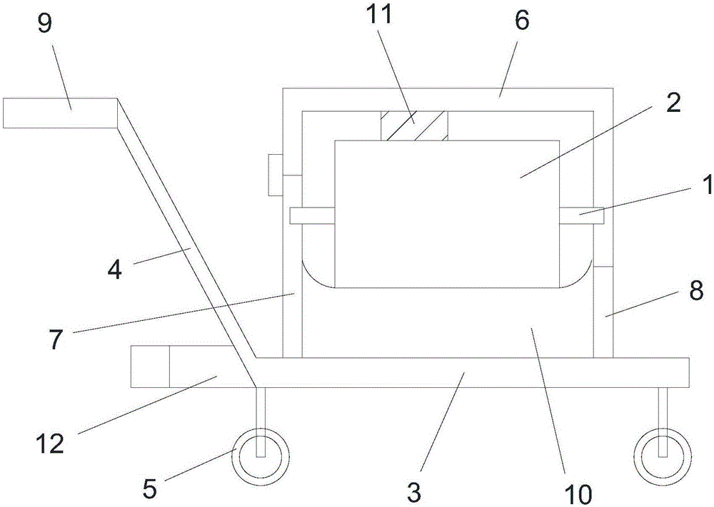
[0031] see figure 1 , the present invention provides a new type of roller transport vehicle, the roller includes a roller 1 and a sleeve 2 sleeved outside the roller 1, including a chassis 3, a push-pull arm 4 and a fixed frame;
[0032] The bottom four corners of the chassis 3 are provided with cart wheels 5, the bottom of the push-...
PUM
 Abstract
Description
Claims
Application Information
 - Generate Ideas
- Intellectual Property
- Life Sciences
- Materials
- Tech Scout
- Unparalleled Data Quality
- Higher Quality Content
- 60% Fewer Hallucinations
Browse by: Latest US Patents, China's latest patents, Technical Efficacy Thesaurus, Application Domain, Technology Topic, Popular Technical Reports.
© 2025 PatSnap. All rights reserved.Legal|Privacy policy|Modern Slavery Act Transparency Statement|Sitemap|About US| Contact US: help@patsnap.com